
Efficient Integral Thermal Management for Battery-Powered Electric Vehicles with Long Range
Dr.-Ing. Christian Möser | Maximilian Flack
In electric vehicles, the travel distance out of one battery charge significantly depends on the ambient temperature. For example, at an ambient temperature of -7 °C compared to 23 °C, the travel distance provided by one battery charge in the WLTP cycle can fall as low as 60 %. Heating the cold electric drive components and the vehicle interior from low temperatures increases this negative effect even further. On the other hand, fast charging requires the battery cell temperature to be held in a tight window at 40 °C, as the battery charges particularly fast in this condition at low losses. Thermal management therefore has a decisive influence on the performance relevant to the customer such as driving range and vehicle comfort and becomes a brand-defining factor for automotive manufacturers. Schaeffler offers a comprehensive modular system of different thermal management solutions for electric vehicles. These include efficient and versatile individual components, highly integrated thermal management systems, and complete drive concepts in which motor, transmission, power electronics, and thermal management are integrated into a ‘4-in-1’ system, optimized as a unit.
Thermal management requirements in electric vehicles
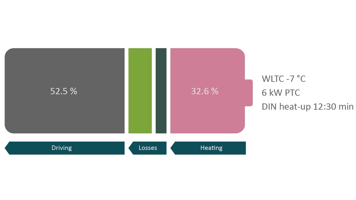
Battery-driven electric vehicles exhibit considerable potential in terms of real driving range out of one battery charge at particularly high or low ambient temperatures, as well as the period of time required for fast charging. The main reasons are air conditioning and climate control in the vehicle interior during cold winter temperatures, friction losses in the powertrain, and the reduction of the charging or discharging efficiency of the traction battery down to the point that recuperation is no longer feasible. Further, friction losses in the transmission due to higher oil viscosity contribute to reduced efficiency. Due to the high efficiency of electric drives in comparison to internal combustion engines, their dissipated heat is too low for vehicle interior climate control. Also, the actual temperature level (inlet temperature) does not achieve the required temperature of 50 to 60 °C for heating the interior of the vehicle which means that additional heating measures are necessary. Figure 1 shows a typical split of the energy requirement in the WLTC (Worldwide harmonized Light duty Test Cycle) at a low ambient temperature of -7 °C.
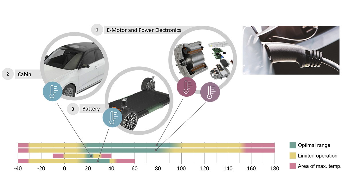
Heating the cold components of the electric drive from low temperatures up to the operating temperature has an even greater negative effect on the energy requirement. Lithium-ion batteries play a particularly important role and the reactivity of the battery’s lithium, nickel or cobalt, graphite, and copper chemical components is dependent on their temperature. The ideal discharge temperature of lithium-ion batteries is 20 °C. Below this ‘comfortable’ temperature, the charging/discharging efficiency of the traction battery and therefore the vehicle range decreases, as well as the battery lifetime. At lower ambient temperatures, the battery must, therefore, be heated up to its operating temperature quickly after the vehicle operation has started, Figure 2. While traveling, the thermal management must, therefore, keep the lithium-ion battery within a temperature range between 25 °C and a maximum of 45 °C to ensure full performance at high efficiency.
On the other hand, for fast charging the battery temperature should be increased to approximately 40 °C as at this level the internal resistance of lithium-ion batteries is at its lowest, enabling high C-rates (relationship between charging current and capacity) in spite of greater resistive losses. The battery then charges particularly fast with low losses. In terms of keeping time spent at the charging point to a minimum, it is expedient to carry out this conditioning while driving. The battery also heats up while charging. The thermal management system must therefore ensure the optimum charging temperature is maintained by transporting the heat out of the battery. If this temperature is exceeded, the charging current has to be derated in order to prevent irreversible degradation of the traction battery. Consequently, the C-rate as an indicator of the charging speed decreases and the charging process takes a correspondingly longer time. Fast charging in particular generates extremely high-power dissipation in the form of heat. This heat is transported away via the coolant and the cooling system, i.e. the vehicle's air conditioning system, and is dissipated into the environment. Charging the vehicle parked at a charging station is a particularly challenging situation as there is limited capability to transfer the heat into the environment.
Thermal management has become increasingly important in the development of electric vehicles and their drive components. This is due to the direct relationship between the energy requirement for the correct thermal control and the battery range as well as the influence on the fast charging process. Thermal management controls the various temperature ranges for the vehicle interior, battery, electric motor, and power electronics, as can be seen in Figure 2. In order to be able to offer customized solutions for all customer requirements in the various vehicle segments and performance classes, Schaeffler is pushing the envelope in the development of new thermal management approaches on multiple levels:
- The company offers a set of efficient individual components which can be flexibly integrated into existing systems.
- Components which can interact with optimum efficiency are the main focus when developing thermal management systems. The required cooling and heating functions for a specific vehicle drive the decision-making process in terms of the best architecture and, therefore, the components.
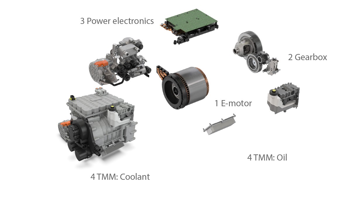
- Schaeffler is developing the thermal management on the hierarchically superordinate drive level together with the electric motor, transmission, and power electronics as an integral part of the entire system. The subsystems can be optimally matched to each other in this 4-in-1 drive system, Figure 3, which allows further improvements to be achieved in the battery range and the rapid charging time without having to take greater system costs on board. This is an important factor, particularly for electric vehicle platforms in the future. The thermal management system applied must demonstrate a high performance scalability and be able to accommodate different vehicle interior volumes, comfort requirements, performance classes, and drive system configurations.
The individual components of the Schaeffler thermal management and the overall system functions are described below with examples.
Thermal management architecture for electric vehicles
From the point of view of the thermal management, the vehicle system primarily comprises individual heat sources and heat sinks which interact with each other in different ways depending on the driving situation and, therefore, either satisfy or create cooling and heating tasks in addition to their actual function. In electric vehicles, these are usually the electric motor, the power electronics, the traction battery, and the vehicle interior in addition to the environment which is generally an important heat source or sink.
Electric motor
The Schaeffler electric motor for the 4-in-1 drive system is specifically designed for everyday operating ranges [1]. The adaptive temperature control via the thermal management allows efficiency benefits of up to 4 % to be implemented depending on the operating conditions. At the same time, the electric motors are a valuable heat source due to their comparably low thermal load and their construction with direct oil slot cooling which allows direct heat dissipation. Schaeffler uses the electric motor as an additional electric booster heater in the thermal management system.
Power electronics
The power electronics also have an additional heating functionality in the thermal circuit. Schaeffler can generate 5 to 8 % of the peak output without any negative effect on the component service life through clever control. This applies even for stationary vehicles. The power electronics supply a stator current without producing any torque. This heats the stator windings without rotating the motor. There are also heat losses in the stator’s laminated core due to hysteretic remagnetization.
Battery
The traction battery can be used as a thermal buffer accumulator in the powertrain, amongst other things. A homogeneous temperature distribution within the battery must be taken into consideration when designing the battery cooling system. Disproportionately high hot zones, or hot sports, on individual cells in the battery pack can lead to a loss of performance due to limitations on the maximum mean battery pack temperature or even to irreversible damage to the accumulator to the point of thermal runaway.
Vehicle interior
The thermal management must provide the required heat flows for climate control of the vehicle interior extremely efficiently. The requirements vary depending on the vehicle class. To ensure a high degree of modularity despite the variety, further measures must be implemented both now and in the future which focus even more on passengers’ vehicle interior requirements. This includes, for example, thermal surfaces or independent precise control of the air routing. Schaeffler is aware of these thermal management design options and is developing scalable solutions in the cooling and coolant circuit for a range of different configurations tailored to the vehicle interior climate control measures.
Figure 4 shows an example of a Schaeffler thermal management architecture for a typical electric vehicle with a driven axle. Unlike in vehicles with an ICE where only one coolant circuit is generally used for the drive components, temperature control of the components in an electric vehicle is usually provided by combining at least one cooling and one refrigeration circuit. While the coolant is only used to transport heat in the cooling circuit and is only present as a liquid, the refrigeration circuit uses the refrigerant’s physical properties of energy release or absorption when changing physical state from liquid to gas and vice versa. When designing the entire system and therefore specifying the individual components, Schaeffler follows an operating strategy in which all technical and comfort-related demands on the thermal management system can be met with a simple design and fewer components. Key elements here are operating conditions relevant to customers and for homologation which occur particularly frequently in day-to-day usage or which generate a high energy demand.
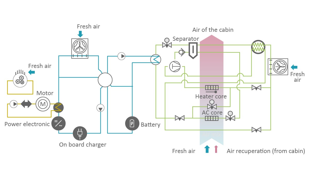
Coolant circuit
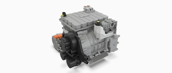
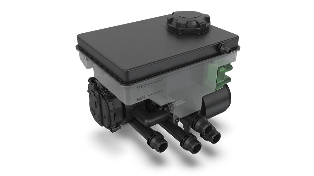
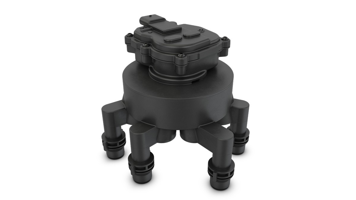
Figure 4 (right) shows a coolant circuit which facilitates heat transfer and buffering. At the heart of this circuit is the Integrated Coolant System (ICS), Figure 5, with its integrated pumps, sensors, and the central coolant regulating valve which distributes the heat flows. Unlike the established rotary valves [2], the integral central regulating valve for the coolant, Figure 6, is optimized for the use cases and temperature ranges of electric vehicles. These applications require a component with a control logic which can be integrated into other systems on a modular basis. To achieve this, the contour of this rotary disk has an axial design and thus a lower assembly height. Schaeffler has developed the ICS as a modular configuration so that it can be adapted to various vehicle classes on a single platform as well as vehicles with two- or four-wheel drive. The system can also be extended for use in a fuel cell vehicle to accommodate further functionality, particularly for operating the fuel cells in cold conditions. The modular components also offer high integration flexibility into different spaces. The output of the integrated water pump is scalable to enable a range of volume flows. This also applies to the coolant valve and its actuator. Temperature and coolant level sensors are also integrated and can be connected centrally. The components are electronically-controlled via a central unit and an LIN interface communicates with the vehicle. When compared directly to an assembly with individual components, the space required for the integrated coolant system decreases from approximately 16 l down to 8.4 l. In addition to this, the system offers further potential for savings during vehicle assembly line processes at the automotive manufacturer as there are only six assembly steps compared to the previous 22, primarily connecting coolant pipes and electrical connectors.
Refrigerant circuit
Figure 4 (left) shows the refrigerant circuit using a Schaeffler thermal management system as an example. The integrated heat pump function provides access to the heat from the motor, power electronics, and battery and allows heat to be gained from the ambient air, thus increasing overall efficiency. The Schaeffler heat pump system offers a high Coefficient of Performance (COP). The COP value is the ratio between the usable thermal energy produced and the energy required for this. R744 (CO2) is used as the coolant. The reasons for using this are better thermodynamic properties when compared to the synthetic coolant R1234yf (tetrafluoropropene) which makes R744 more suitable for the heat pump operating conditions and more environmentally friendly. R744 is also non-combustible and therefore counts as harmless. R744 also has a GWP (Global Warming Potential) value of 1 which is only a quarter of the potential of F1234yf (GWP = 4) [3, 4] and only a 1430th of R134a.
From a functional perspective, one of the benefits of R744 is the extent of its temperature range. R744 heat pumps still supply sufficient thermal load to heat the vehicle interior, even at low external temperatures, Figure 7 (left). Compare this to the COP of R1234yf systems which decreases extremely sharply from 0 °C. At temperatures from -10 °C, sometimes even at -5 °C, R1234yf systems can only operate with substantial additional costs. A booster heater (COP ≤ 1) is necessary to ensure the vehicle interior is comfortable which has a significant detrimental effect on the efficiency of the entire system such that the benefits of these expensive measures are compromised.
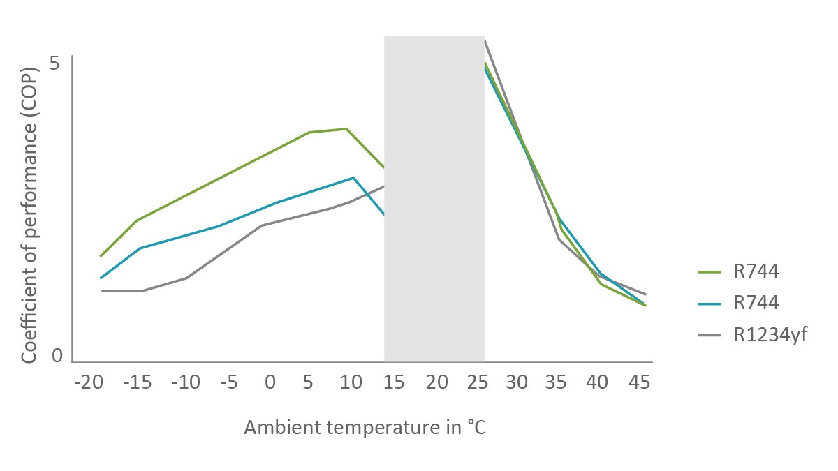
The reason lies in the different thermodynamic/physical properties of both substances. To be able to extract heat from the ambient air at low temperatures, the evaporation process has to take place at an even lower temperature (and therefore at a lower pressure). Even at ultimate evaporation pressures (i.e. the suction pressure for the compressor) of 10 to 20 bar, R744 can be used at evaporation temperatures of less than -20 °C. This means heat can still be extracted from the ambient air even at an external temperature of -20 °C. However, with R1234yf, the suction pressure under these conditions is so low that the compressor would have to create a very high compression ratio which would mean efficient operation would no longer be possible (COP ≤ 1.0). In addition to this, there is a danger that the suction pressure can even fall below atmospheric pressure and the seal tightness of the entire system is no longer guaranteed.
On the other hand, at high temperatures and when the cooling requirement is at its greatest, the R1234yf circuit approaches its limits due to the lower volumetric cooling output compared to R744, Figure 7 (right). As a result of this, very large components have to be chosen for the R1234yf refrigeration circuit for the same cooling output which, on the one hand, increases the space requirement in the vehicle and, on the other, can reduce the efficiency depending on the operating condition. Even with scroll compressors (the current state of the art technology), the displacement volume must be doubled or tripled to be able to ensure the battery is cooled, including during rapid charging, while at the same time meeting potential climate control demands for the vehicle interior. This unavoidable increase in the displacement volume of the compressor in scroll compressors represents a challenge for the development of the mechanical components.
To implement the theoretical benefits of R744 in practice, Schaeffler has adapted the entire refrigerant circuit to the specific features of the CO2 system. Due to R744's different vapor pressure curve, a CO2 refrigeration circuit works with a significantly higher pressure than a circuit with R1234yf which could lead to a loss in efficiency in an inadequately specified system. A combination of two-stage compressors and R744 systems which have a medium pressure input are known from industrial and stationary applications. Schaeffler is using this approach for the first time anywhere in the world in the automotive sector and has developed a corresponding concept for electric vehicles.
In conventional, single-stage coolant circuits, the coolant is compressed by the compressor from a low pressure to a high pressure and then returned to a low pressure via the condenser, expansion valve, and evaporator. In the medium pressure process, on the other hand, compressed R744, which has been cooled in the gas cooler, goes through two expansion phases. The first decompression ends at a medium pressure and the R744 at this stage is in a partially liquid, partially gaseous state. The gaseous component is fed to the compressor. The remaining liquid component, on the other hand, effectively goes through a second circuit: It is expanded in another expansion valve and then evaporated in a relatively wide enthalpy range. It then flows into the low pressure stage of the compressor where it is once again compressed to the high pressure level. Due to the medium pressure process, there is a reduction in the mass flow component which the compressor has to compress from a low pressure to a high pressure. This allows the compressor to operate more efficiently compared to a single-stage process. In addition to this, intermediate cooling takes place in the compressor due to the medium pressure gas, further optimizing the circular process.
Rolling piston compressor
In terms of construction, the scroll compressors used in today’s electric vehicles do not facilitate sensible integration of a medium pressure input as the additional inlet would only be open for a very short period of time. Schaeffler therefore uses rolling piston compressors for the medium pressure input concept. The coolant is compressed in a closed cylindrical chamber in which an eccentrically supported rotary piston rolls around the internal wall. As the cylinder can be accessed easily from the outside, the medium pressure input can be used across almost all the angle of rotation.
Schaeffler offers rolling piston compressors with and without medium pressure input to allow demands from a range of vehicle applications to be accommodated. A greater degree of efficiency is therefore achieved using R744 than with conventional electrified scroll compressors. In the current configuration, the scalable series of Schaeffler rolling piston compressors with medium pressure input in a single, two, three, and four cylinder design has the following technical specifications:
- Displacement volume: 4.5 to 18 cm3
- Refrigeration capacity: maximum 18 kW at 8,000/min
- Mechanical drive power: 5 to 13 kW
- Power supply voltage: 800 V.
Functional integration
Schaeffler has taken a platform-based approach to the development of components for the coolant and refrigerant circuit. This means it is possible to design the entire system flexibly in response to various requirements. For example, it is possible to have a configuration with or without a heat pump function in the refrigeration circuit and with various outputs for the refrigeration system. As the ICS example has shown, the distinctive modularity is a singular feature of the Schaeffler concept. Another feature is the maximized performance density due to the high degree of integration. To achieve this, a number of thermal management and propulsion functions and the required components are combined in a single unit and the number of interfaces between the individual components is minimized. One example is the refrigerant distribution plate which comprises many components from the heat pump circuit such as expansion valves, coolant channels, and separators/accumulators. This means the entire system is easier to integrate due to the central arrangement, thus minimizing assembly costs at the automotive manufacturer as many components are supplied preassembled. Furthermore, complicated arrangements of pipework and hoses are no longer required which also improves accessibility when servicing the vehicle.
4-in-1 drive system
Schaeffler is realizing exceptionally high potential in terms of savings and efficiency in thermal management by integrating the system into the 4-in-1 drive module, Figure 8. Here, the electric motor, transmission, power electronics, and thermal management are combined into one unit [1]. By adapting the relevant assemblies and components to the requirements of the entire system, the functions can be optimized to specific operating conditions so that the system architecture can be simplified without losing or even gaining performance capability. The resulting added value for the customer results in the sum of the individual systems (electric motor, transmission, power electronics and thermal management – ‘3 plus 1’) in the 4-in-1 module being greater than four.
When designing the 4-in-1 system, it is possible to focus specifically on the relevant individual performance parameters depending on the requirement. This results in the following typical system configuration for the drive on a C-segment vehicle with front wheel drive, a gross weight of 2,000 kg, maximum speed of 160 km/h, and acceleration potential of 0 to 100 km/h in 7.5 seconds:
- 800 V traction motor with slot cooled stator and 160 kW output with a central hydraulic supply
- Parallel axis transmission with optimized efficiency (axle torque 3,200 Nm)
- R744 refrigeration circuit with medium pressure level for maximum efficiency
- Cooling circuit system largely located in the housing of other subassemblies
- Centralized electronics which act as a domain controller and which also include the output stages for the traction motor and climate control compressor which are fitted with silicon carbide (SiC) semi-conductors.
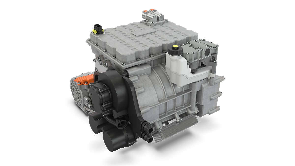
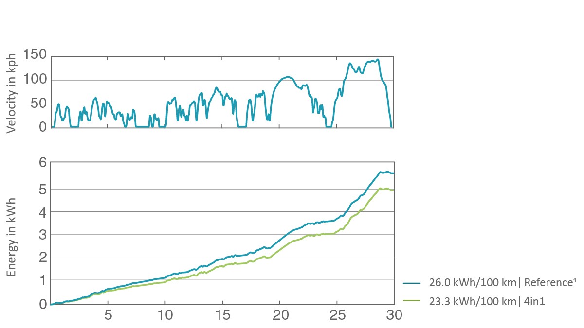
Figure 9 shows the results of a simulation of the system in the WLTP (Worldwide harmonized Light Vehicle Test Procedure) test cycle for a low external temperature of -7 °C. Compared to a conventional, non-modular drive system (blue curve), the Schaeffler 4-in-1 concept (green curve) offers considerable potential for savings. Depending on the design of the vehicle application, automotive manufacturers can make use of the energy savings to reduce the size of the traction battery and therefore make it more cost-effective, or to achieve a greater range without changing the size of the battery.
Summary
In electric vehicles, the distance available from one battery charge is heavily dependent on the external temperature. Thermal management therefore has a decisive influence on vehicle properties relevant to customers and becomes a brand-defining factor for automotive manufacturers. At the same time, the temperature and operating ranges considered as part of homologation are being extended even further by new regulations and procedures such as the -7 °C cycle in the WLTP and Green NCAP. The means an efficient and effective thermal management system will prove more beneficial. Schaeffler offers a comprehensive modular system of different thermal management solutions for electric vehicles. This includes both coolant and refrigerant circuits with heat pump systems. When designing the entire system and therefore specifying the individual components, Schaeffler follows an operating strategy in which all technical and comfort-related demands on the thermal management system can be met with a simple design and fewer components. The scope of Schaeffler’s solutions ranges from individual components which can be efficiently and flexibly integrated, via highly-integrated thermal management systems, to complete drive concepts comprising the motor, transmission, power electronics, and thermal management as a single unit, optimized in the system.
The Schaeffler heat pump system provides high levels of efficiency with minimal space requirements. This increases the range of electric vehicles without having to alter the battery capacity, or provides an opportunity to reduce the size of the battery with the corresponding cost reductions but the same reach. Focusing on the environmentally-friendly and non-combustible coolant R744 will future-proof this approach for automotive manufacturers. Schaeffler offers the integration of a medium pressure process as an optional extension for the scalable and efficient refrigerant compressor which increases the efficiency potential further at the system level. Schaeffler is using this approach for the first time in the world in the automotive sector.
At the drive level, Schaeffler integrates the thermal management system with the electric motor, transmission, and power electronics to create a 4-in-1 drive system. The subsystems can be optimally matched to each other which allows further improvements to be achieved in the battery range and the rapid charging time without having to take greater system costs on board. The resulting added value for the customer means the sum of the individual systems (electric motor, transmission, power electronic plus thermal management system – ‘3 plus 1’) is greater than four.
[1] Pfund, T.: Efficient Scale-Up to Volume Production of Innovative Electric Motors and Power Electronics. Bühl: Schaeffler Kolloquium, 2022
[2] Tuncay, V.; Weiß, M.: Intelligent Thermal Management for Hybrid Powertrains. Baden-Baden: Schaeffler Kolloquium, 2018
[3] Infraserv GmbH & Co. Höchst KG (Hrsg.): Das Kältemittel R 1234yf und seine Eigenschaften.https://www.infraserv.com/de/leistungen/facility-management/expertenwissen/f-gase/kaeltemittel/spezifische-kaeltemittel/, abgerufen am 25 November 2021
[4] Großmann, H.; Böttcher, C.: Pkw-Klimatisierung. Heidelberg: Springer, 2020