Efficient Scale-Up to Volume Production of Innovative Electric Motors and Power Electronics
Thomas Pfund
The idea of having a standard electric motor that can be used in hybrid modules, dedicated hybrid transmissions, and electric axle drives will never become reality because the requirements differ so greatly. Despite this, to enable rapid scale-up to volume production for as many vehicle classes and markets as possible, Schaeffler has developed a technology platform for flexible and economical electric motor manufacturing. Alongside this, a pilot plant for testing agile electric motor manufacturing technologies is being built in Bühl as the first of its kind in the world. Process and product innovations complement and promote each other, as is shown in this contribution by means of new electric motors as well as power electronics with an efficiency of more than 99%.
Status of manufacturing ramp-up
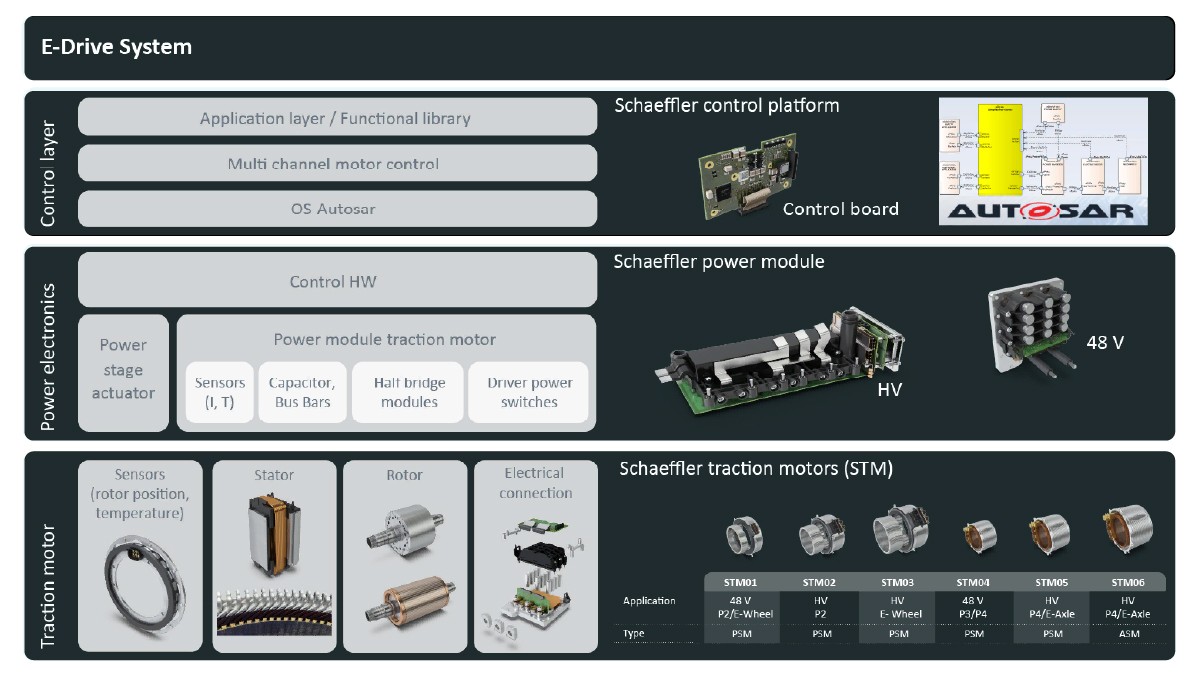
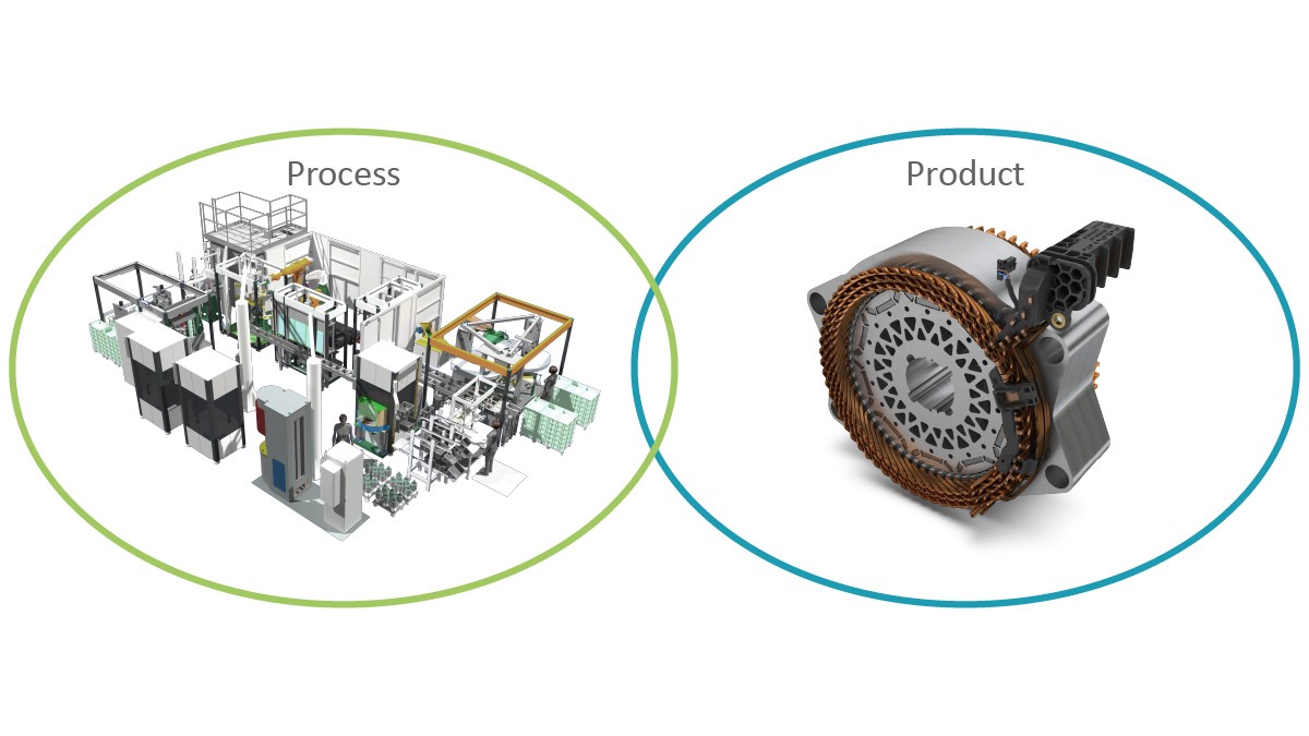
At the 2018 Colloquium, Schaeffler presented a modular and highly integrated technology platform for electric powertrains. An article from 2018 [1] stated that “electrified vehicles will reach high volumes in the coming decade and the level of mechatronic integration will increase significantly”. To accommodate the variety of powertrain variants already emerging then, combinable electric motor, power electronics, software, and overall system solutions for which development was already quite advanced were presented; see Figure 1. However, four years ago, scale-up to volume production of all-electric powertrains was only getting started.
Over the last four years, focus has been not just on developing innovative products but also on bringing the manufacturing processes for the individual components and systems up to the stage where industrial-scale manufacturing of electric powertrains in high volumes with maximum flexibility is possible. To that end, a suitable technology was selected for each manufacturing step, tested, and released for the manufacturing platform; see Figure 2.
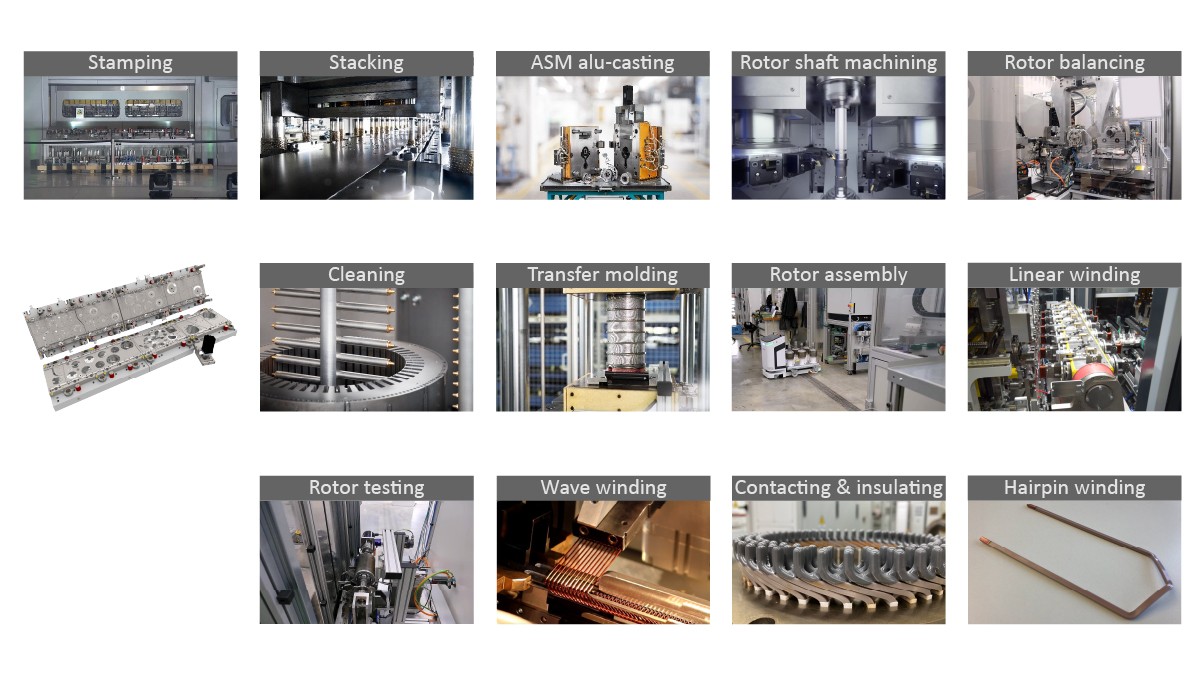
One example illustrating how the development goals of “efficiency” and “flexibility” can be united in highly automated manufacturing facilities is the tooling concept for stamping. To enable a high degree of reusability across all product variants as well as flexibility in the setup processes, a modular, double-row concept was developed with the help of Schaeffler’s in-house toolmaking facilities. It uses the so-called progressive stamping approach. This means that the rotor and stator laminations for a motor are both stamped in one cycle. Sheet metal utilization is thereby optimized and scrap is minimized. A high level of flexibility is also needed for the process step of “winding” to accommodate not only the individual tooth winding but also the other established methods of hairpin winding based on the insertion of copper bars and continuous hairpin winding. Through the acquisition of the special machine manufacturer Elmotec Statomat in late 2018, Schaeffler greatly expanded its expertise in the field of winding technology. In the manufacturing of rotors for permanent magnet electric motors, Schaeffler makes use of transfer molding, in which the injected thermosetting plastic encapsulates the magnets and hardens. The full encapsulation protects the magnetic materials from environmental influences and thereby makes passivation and elaborate surface treatment unnecessary. The technology platform also covers process steps needed for manufacturing asynchronous machines; one example is aluminum die casting for the rotor cage.
Because Schaeffler has long been pursuing a value creation strategy that is based on the motto “In the region, for the region,” the technology platform is ready to be deployed globally. The technology and the production equipment are globally standardized. With such a strategy, it is also possible to respond flexibly to volume fluctuations in individual regions. By 2026 Schaeffler will have invested more than 500 million euros in building up manufacturing capacities at the plants in Bühl (Germany), Szombathely (Hungary), Taicang (China), Wooster (USA), and Puebla (Mexico). The Bühl plant will take on the role of lead plant, in whose pilot plant new technologies for agile electric motor manufacturing will be developed. The technologies tested in low volumes in Bühl will then be used in all plants worldwide.
Variety of applications
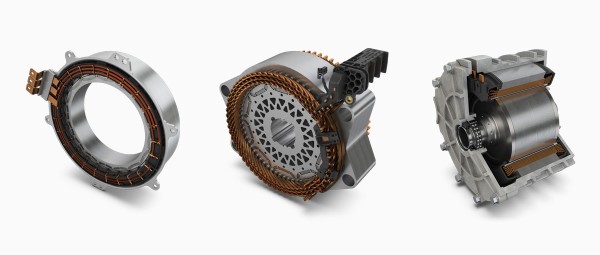
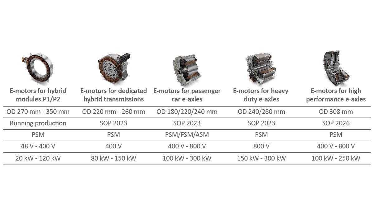
The electric motors that are currently being manufactured and that will be manufactured in the near future by Schaeffler differ significantly in terms of type as well as design and specifications, as can be seen in Figure 3. The reason for this diversity in terms of motors is the diversity seen in the vehicle and powertrain architectures. The electric powertrain forms that dominate the market can be categorized as electric axle drives, dedicated hybrid transmissions, and hybrid modules.
It is ultimately the system-level requirements that determine which motor type and individual technological components are selected. For example, for hybrid modules, the installation space requirements are decisive, especially since not only the motor but also one or more clutches must be situated in the tight space between the internal combustion engine and the transmission. For this reason, the value for active length is typically low, but the diameter is relatively large. This speaks for the use of single tooth winding. With a process developed by Schaeffler for mechanical postcompression of the windings, a high slot fill factor can be achieved. The combination of a special electric motor design, the winding process, and subsequent compression yielded an efficiency of 97.3% for a motor with an active length of 34 mm. This was not previously possible for this technology and motor type. For motors with the highest value for active length, in contrast, Schaeffer uses so-called distributed windings, which can be executed as classic hairpin or continuous hairpin windings.
Another example showing how much the decision in favor of individual technologies depends on the overall system is the use of permanent magnet synchronous machines versus asynchronous machines in electric axle drives. Permanent magnet machines are attractive options in many cases for the main drive axle due to their high power densities. If a second electric axle is added to such a vehicle to yield an all-wheel drive that can be switched to and from, the asynchronous machine can be advantageous due to the lack of drag torque and raises the overall efficiency of the powertrain. Separately excited synchronous machines are an option if high power densities need to be achieved without the use of magnetic materials. The technology platform from Schaeffler makes it possible to realize the motor type by appropriately varying the rotor while keeping the stator nearly the same.
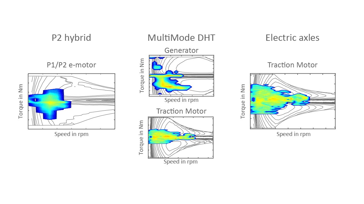
Depending on the powertrain concept, the regions of the torque–speed map that are used can differ considerably; see Figure 4. A hybrid module at the P1 or P2 position often works in generator mode. This is especially true for the first, usually crankshaft-side electric machine in a dedicated hybrid transmission, whereas the second motor is mainly used to provide traction drive. An electric axle drive typically covers the complete driving cycle, or real driving conditions, including higher speeds.
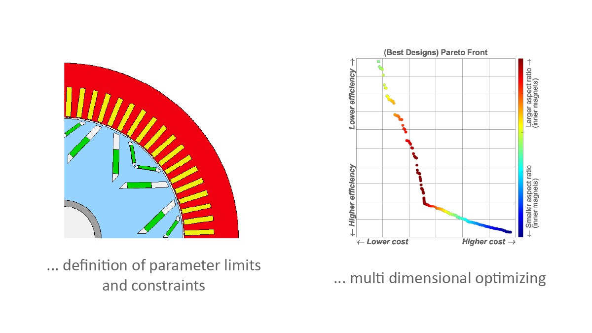
To size an electric motor optimally for a particular application, it is necessary to look at a large number of criteria. Noteworthy ones include performance values, acoustic behavior, efficiency in the driving regions used, installation space, weight, and, of course, costs. This results in numerous conflicts in terms of aims, which cannot all be smoothed over using a standardized solution at the product level, but rather can only be resolved through standardization at the manufacturing level. Additionally, at the product level, there are numerous factors that can be adjusted and thereby the geometry optimized: active length, air gap width, or arrangement of the magnets. It would be hard for a single design engineer to find the optimum in the short amount of time available for development. For this reason, Schaeffler has developed an automated optimization process based on the laws of growth for finding the few promising variants among the nearly endless combinations in a defined time span.
Important for the use of such a multidimensional process is the preliminary definition of the limits that the parameters may be varied within. These limits as well as the available installation space are mainly defined by the manufacturing platform. A simple example showing the geometry variants generated in such a process is shown in Figure 5. Due to the introduced restrictions, the resulting function does not correspond to a classic Pareto front.
Agile volume manufacturing
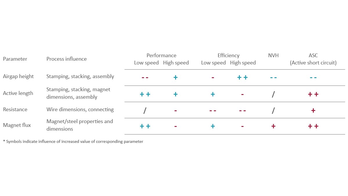
The optimization process described here ensures that the result at the end of the development process is always a motor design that represents the best possible solution on the product side and that can also be manufactured within the scope of the Schaeffler technology platform. Now, for the ramp-up to high-volume manufacturing, a challenge arises in that the properties that the customer desires, such as torque, efficiency, or acoustic behavior, depend on a large number of individual manufacturing parameters. These parameters can vary slightly due to tolerances in the supplied materials and the processing steps, as shown in Figure 6, although target–actual deviations can have positive or negative effects on the motor characteristics. This mean that tolerances can also balance each other out and result in a product after assembly that has exactly the desired properties.
With continuous process monitoring, which is at the heart of all Industry 4.0 approaches, it is possible to detect tolerances in individual components still in the process of being manufactured. As a result, tool settings can be adjusted precisely to match the workpiece in the individual manufacturing steps. In addition, it should be possible during assembly to pair components whose tolerances balance each other out. For this, Schaeffler consistently relies on modularization of manufacturing.
Individual manufacturing modules that can be activated online form the basis for new, agile manufacturing concepts. Linked throughout to ensure minimal cycle times and high throughputs, the manufacturing modules provide the conditions necessary for controlling and combining balancing tolerances.
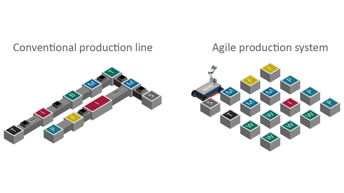
For combined manufacturing of different electric motor variants from applications with low to medium volumes, process modules can be linked by means of automated guided vehicles as shown in Figure 7. The process sequences and the setup operations are then controlled by the AI-based process control technology “on demand.” In this type of “agile manufacturing,” it is even possible to offer alternative technologies, e.g., different winding processes, for some process steps while maintaining the same technology for other steps, e.g., impregnation. It is possible to increase capacities by adding further modules for the respective bottlenecked resource.
For continuous real-time process monitoring, process modules and products must each be described in detail in a separate digital twin, as shown in Figure 8. The digital twins can communicate with each other in two ways:
- Offline: Already during product development, it is possible to check if a specific design can be manufactured in an existing or planned process module. Constant comparison at the tool–workpiece level makes for a more focused and rapid development process.
- Online: The digital twin of a product stores essential data about the product’s own manufacturing as it passes through the manufacturing process. These data can then be called up by the digital twin of the process module in the next manufacturing step, for example, for the purposes of varying individual processing parameters or implementing function-oriented process control in the assembly.
Process and product innovations
The close linking of processes and products necessarily results in strong interactions between them when technical innovations are introduced. This is demonstrated below by means of selected new developments. Process innovations primarily serve to expand the product design limits, whereas product innovations are primarily concerned with further improving the customer-relevant properties of electric motors within the expanded limits.
Examples of Process Innovations
Continuous hairpin winding provides a few advantages, which have already been presented elsewhere [1]. Especially noteworthy is the elimination of welding in the end winding, which – when compared with the hairpin technology – reduces the axial installation space and enables a high conductor packing density. Moreover, continuous hairpin winding can handle thinner conductors more easily than other flat wire winding technologies can; this has a positive effect on the frequency-related losses.
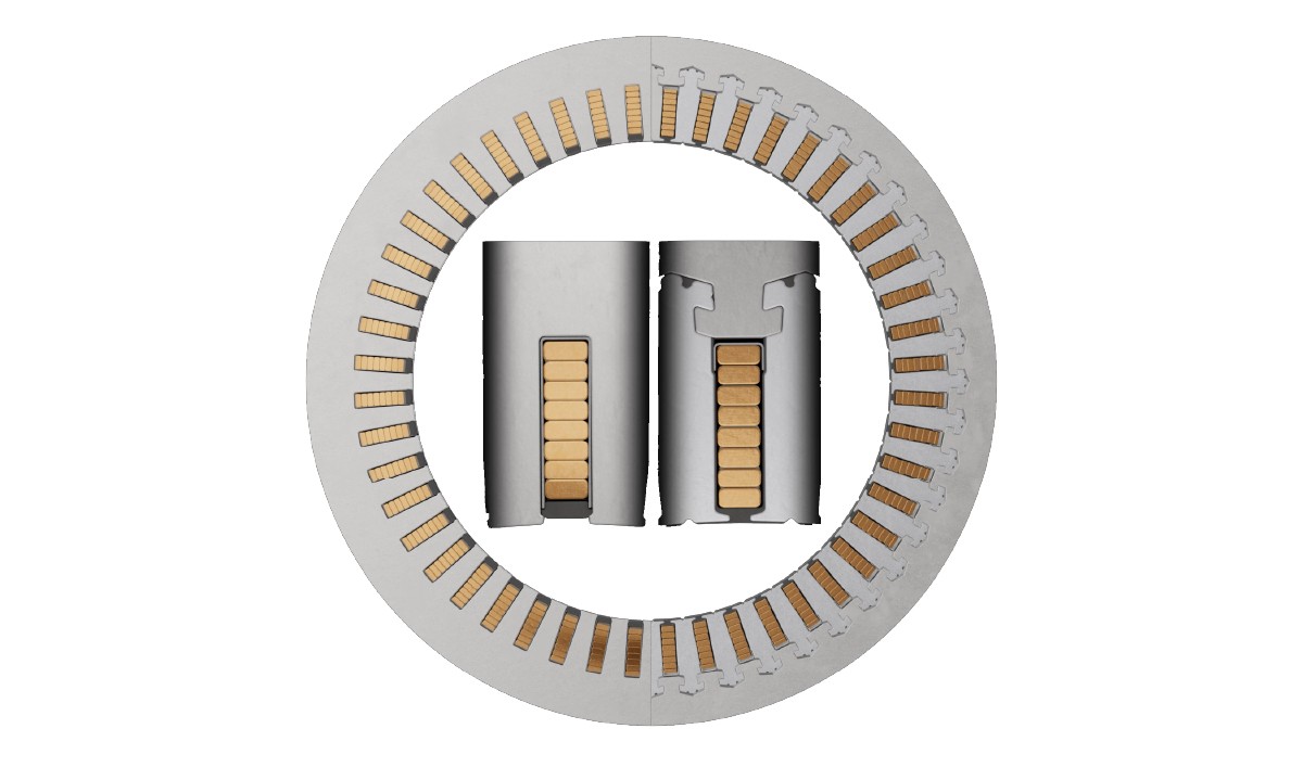
In light of this, Schaeffler is developing a second-generation continuous hairpin winding in which the yoke and teeth of the stator are designed as separate components, as shown in Figure 9. This design enables winding from the outside because the yoke is only attached at the end. This eliminates restrictions on the stator diameter. In addition, due to the lower joining tolerances and precompression of the winding, a higher slot fill factor can be achieved. The design-based closed slots decrease the excitation by harmonics and thus prevent torque ripple. The stator can potentially be built to completion to reduce sheet scrap. Finally, the closed slots can also be used for slot cooling, which enables very effective heat dissipation and thus a high continuous power for the motors.
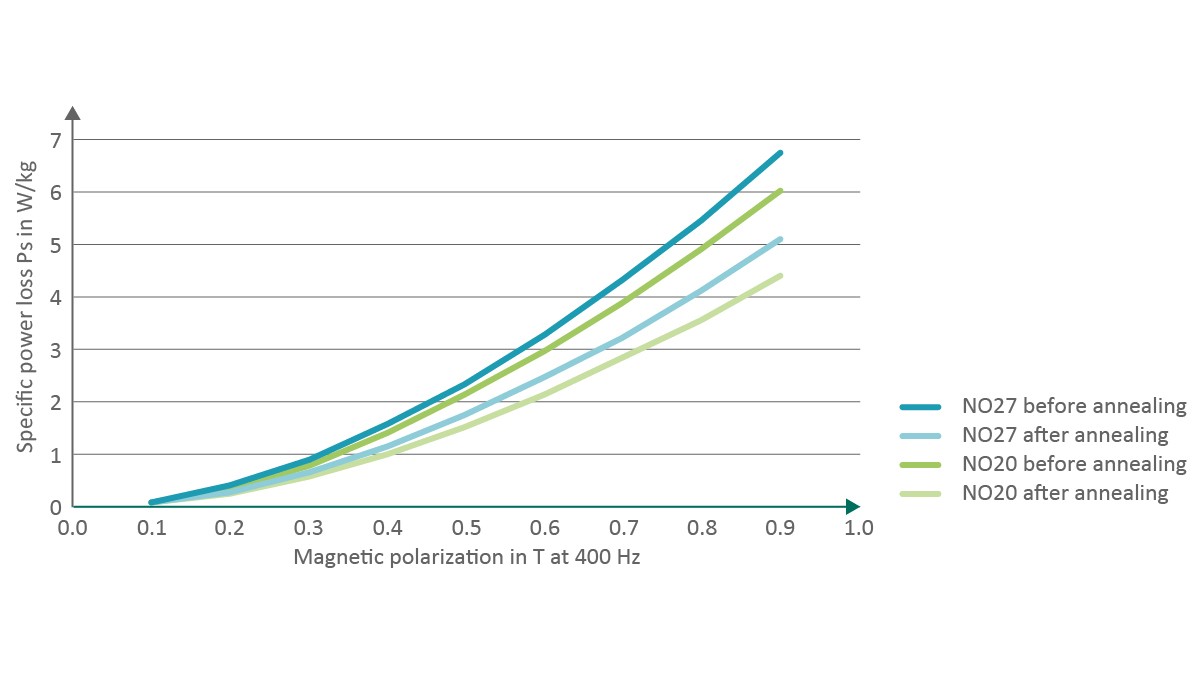
Another process innovation is the annealing of the stator laminations, which enables the microstructural defects produced during the processing to be healed. The higher level of material homogeneity results in lower specific losses during magnetization. The effect of annealing is significant compared with the effect of decreasing the lamination thickness, as the measurement results given in Figure 10 show.
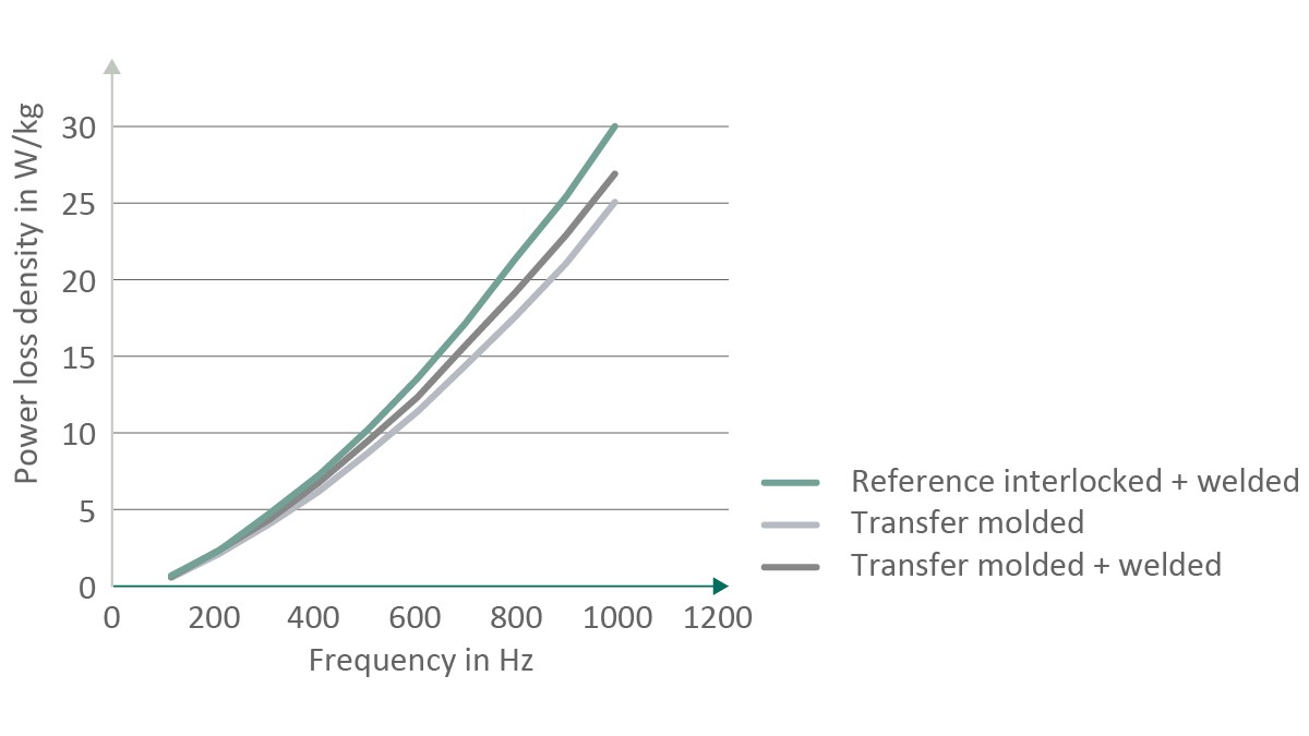
This is followed by assembly and joining of the stator laminations. The manufacturing process that is common in volume manufacturing is mechanical interlocking . It is a low-cost process because sheet coated with a single layer only can be used and stacking is done right in the stamping die, usually with subsequent welding. However, the required fastening elements create conductive connections between the laminations, which promotes eddy current losses. Stacking can alternatively be done using baked enamel (full-surface bonding); this avoids current transfer points and leads to very precise positioning of the laminations. However, this process increases the manufacturing costs because sheet coated with two layers is used and an additional process step is needed for curing of the baked enamel.
For this reason, Schaeffler has developed a transfer molding process in which the stator laminations are mechanically connected through injection of a fast-curing polymer. It combines the advantages of both processes to allow very precisely aligned stator and rotor stacks to be achieved with electrical steel coated with a single insulation layer. There are no electrically conductive connections between the laminations, so the effect on the power loss is also favorable. See Figure 11.
Examples of Product Innovations
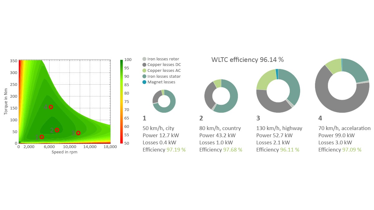
Current electric motors that are executed as radial flux machines already have very high efficiencies. Figure 12 shows the efficiency at various operating points relevant to real driving conditions for a state-of-the-art electric motor for an axle drive. The power loss that still occurs has different causes depending on the operating point. The relationship can be described in simplified terms as follows: At the low power required for city driving, the core losses in the stator dominate; the share that these losses make up decreases with increasing load. In contrast, with increasing output power, the share of copper losses increases; at high loads, these losses can make up three-quarters of the total power loss.
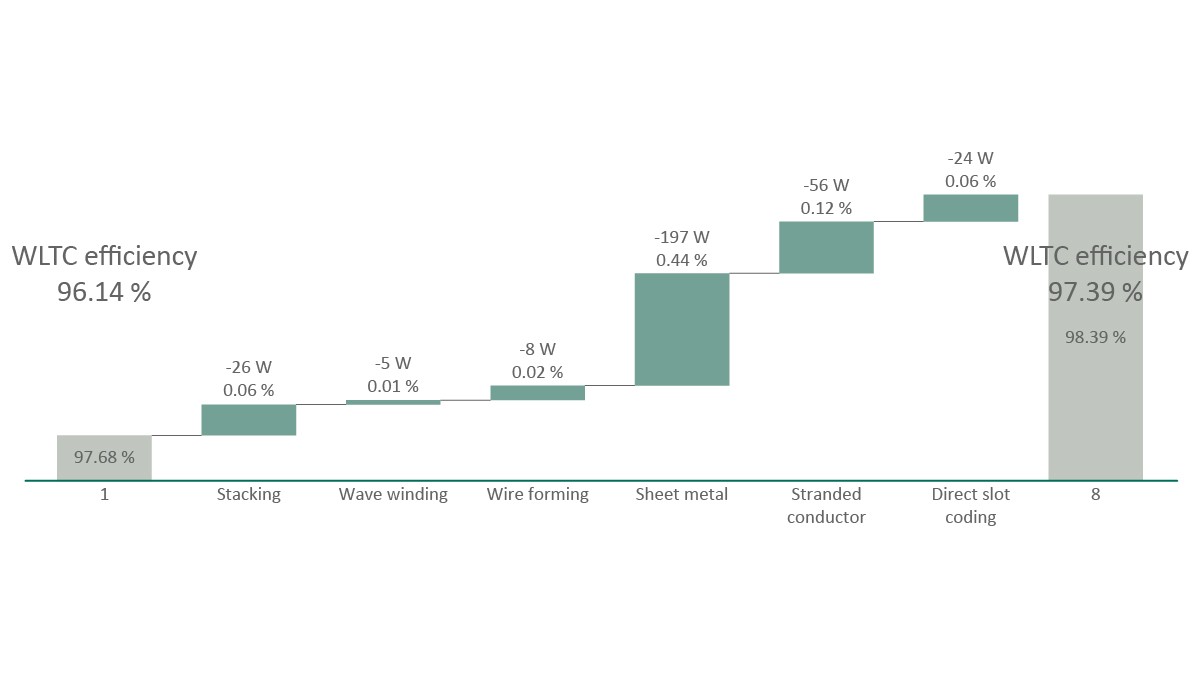
If the above-mentioned technologies are adapted to a motor that has a mean WLTC efficiency of 96.05%, the power loss at the individual operating points can be noticeably improved, as is shown in Figure 13 at operating point 2 for typical secondary road driving. The new type of continuous hairpin winding and the posttreatment of the stator laminations have the greatest effect. This results in an overall improvement in the WLTC efficiency of more than 1 percent. This example shows that the close interlinking of product and process development pursued by Schaeffler ultimately leads to better end customer-relevant electric powertrain properties.
With the measures described here, the electric motor comes very close to an ideal drive in terms of efficiency. The main challenge remaining is the installation space required if very high-performance powertrains – for example, with two motors on one axle – are to be realized.
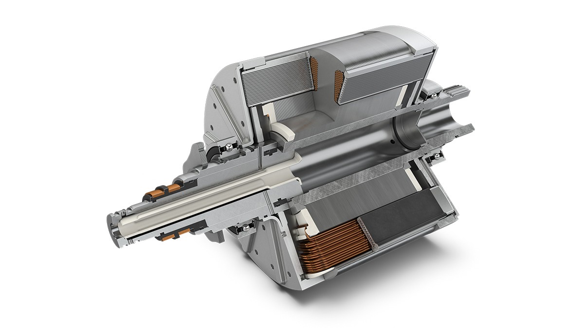
Furthermore all permanent magnet synchronous machines the availability of the magnetic materials in the rotor presents a challenge. A possible solution is provided by the separately excited synchronous machine. Schaeffler is therefore currently developing such an electric motor in which the disadvantage of this type of machine principle is avoided from the start: the continuous flow of current to the rotor leads to comparatively high ohmic losses, especially in the lower speed range. For this reason, Schaeffler has adapted the principle of slot cooling for the rotor; see Figure 14. Through oil cooling right on the windings, a temperature-related increase in ohmic resistance is largely avoided.
Power electronics
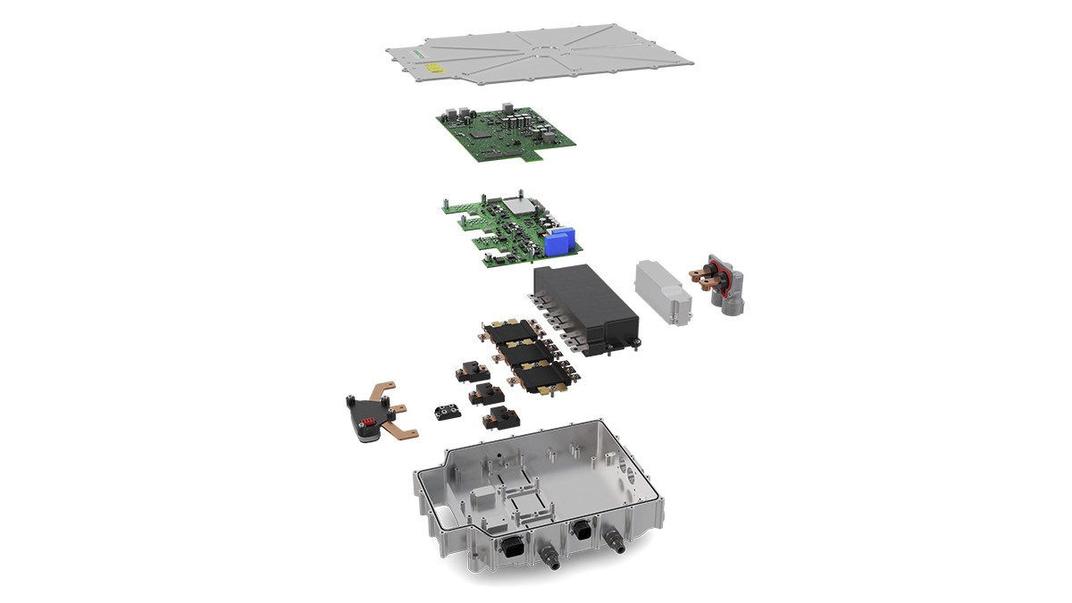
However, a pure improvement in the efficiency of the electric motor does little good if the quality and thus the efficiency of activation is not also improved. That’s why Schaeffler has acquired the know-how for integrating the power electronics of external partners for powertrains operated at 400 V. Integration includes both the hardware – up to the 4in1 electric axle and the software for the complete powertrain control. For 800 V architectures, Schaeffler has developed its own silicon carbide semiconductor-based power electronics for use both in passenger vehicles and in commercial vehicles; see Figure 15. Here, too, the integration expertise covers the complete powertrain, including thermal management. The basis for the software integration is an internal Schaeffler platform that covers all power electronics subfunctions. The model-based design enables integration of software functions from customers or other external partners.
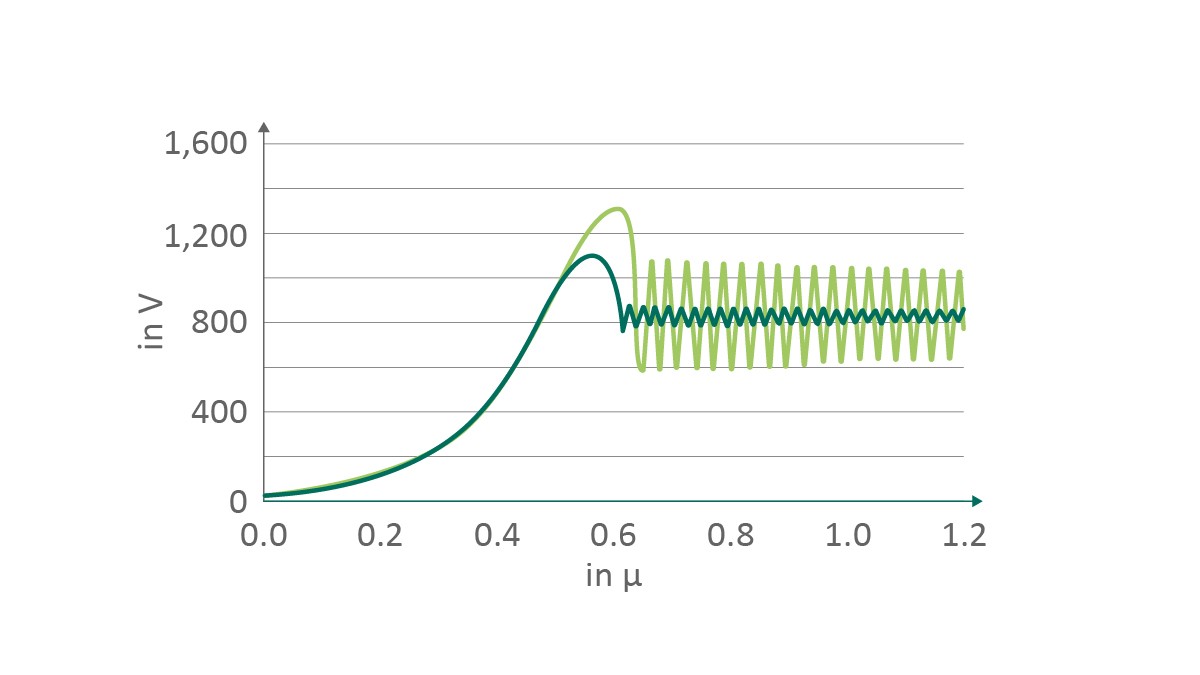
For the power electronics, too, Schaeffler develops process and product innovations using a cooperative design approach to achieve the best possible electrical characteristics. In close cooperation with suppliers and partners, Schaeffler lowered the inductance of the half-bridge modules by 7%, the capacitors by 15%, and the lead frames by 20%. This resulted at a high switching frequency in considerably reduced voltage fluctuations; see Figure 16. The lower amplitude enables higher switching frequencies and also leads to much less loading of the electronic components and a corresponding positive effect on the service life.
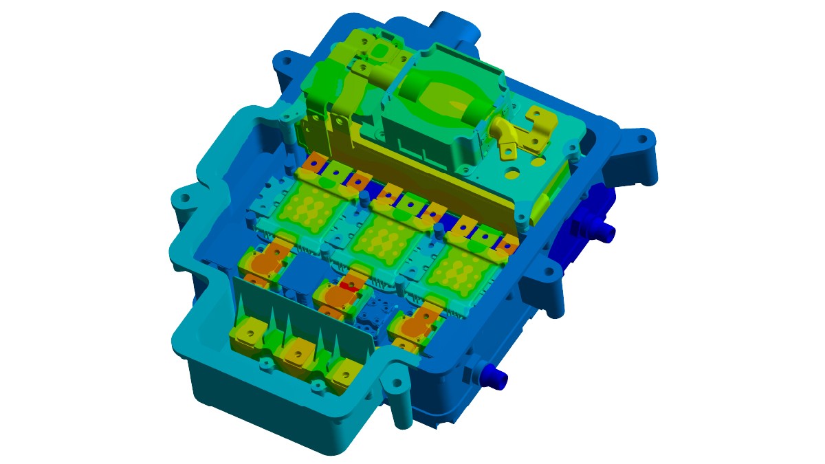
Cooling is decisive for the continuous power that can be switched via power electronics and the service life of the electronics. Schaeffler therefore works with water cooling integrated into the housing. It is designed with all current-carrying components (power switches, lead frames, capacitors) connected to the heat sink. This yields a homogeneous temperature distribution at a high continuous load; see Figure 17.
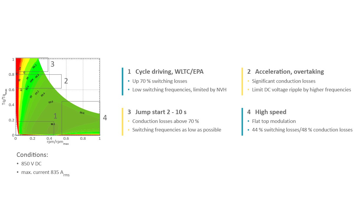
The Schaeffler power electronics have outstanding efficiencies, with the maximum value exceeding 99%. This is only possible because the optimized hardware is combined with the right flexible activation process for each operating region; see Figure 18. At low loads and speeds, the switching losses dominate and can be reduced through a reduction in switching frequency as far as the acoustic behavior permits this. If a high torque is requested, for instance, for a passing maneuver, the conduction losses increase with increasing current. The switching frequency in this region is dramatically increased to limit the amplitudes of the voltage ripple. Full acceleration from a standstill can cause the conduction losses to increase to 70% of the total losses. Here, the switching frequency is reduced further as far as is acoustically permissible to lower the thermal load. For driving at high speed – when the electric motor is operated in the weak map region – the voltage is selectively overmodulated to keep the motor torque as high as possible. The switching and conduction losses are balanced.
One specific feature of Schaeffler’s power electronics is the possibility of integrating the control of additional components. These could be pumps for cooling and lubrication or parking brakes, decoupling units, or air conditioning compressors. As a result, the vehicle manufacturer does not incur any expenses for the integration of additional control units.
Because of the high volume power density of 70 kW/L, little installation space is required for the power electronics. This contributes to allowing very compact overall powertrains at the system level to be realized.
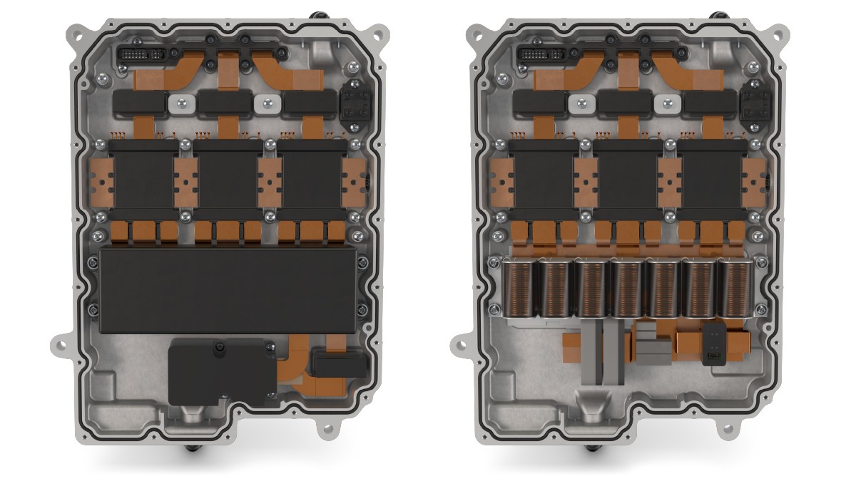
Future generations of 800 V power electronics will feature further improvements in all customer-relevant aspects. There are essentially three innovation fields that enable this. First of all, components such as current sensors, capacitors, or EMI filters, which today are still individually electrically connected via lead frames, can be combined in a housing unit as shown in Figure 19. This not only enables a reduction in installation space but also a reduction in the use of copper, which in turn is reflected in a 13% reduction in conduction losses. Secondly, the housing can be executed at least partially in plastic for reduced weight and costs. If this is done, the components can be placed directly on a nonconducting plastic cooler. The necessary electromagnetic shielding can be achieved via coatings on the relevant housing parts. Thirdly, the power semiconductors can be converted from silicon carbide to gallium nitride (GaN) for the power stage switches. The potential advantage of this material lies in very rapid switching, which enables smoother regulation of the motor and an approximately 20% lower power loss. In addition, growth of GaN semiconductors on silicon substrates provides a cost advantage over silicon carbide.
Conclusion
Due to the rapid proliferation of electric vehicle registrations, fast and economical scale-up to volume production of electric motors and power electronics must be enabled. It must be possible to cover a wide-ranging portfolio with flexibility to cater to the different powertrain topologies. Schaeffler is providing the basis for this with a technology platform that defines and globally standardizes all the relevant production steps – for all motor types, motor sizes, and performance classes. Investments of more than 500 million euros will make it possible to achieve an annual manufacturing capacity of 4 million electric motors in 2029.
Via an automated optimization process, individual application-specific solutions can be found and also produced within the framework of the technology platform. Real-time manufacturing control based on digital twins of product and manufacturing modules enables material and manufacturing tolerances to be compensated for and variants with relatively low volumes to be manufactured economically in an agile manufacturing process.
Process innovations such as annealing of stator laminations and advanced continuous hairpin winding make it possible to boost the efficiency of current radial flux machines even further. Furthermore, the concept for a separately excited synchronous machine that reduces the ohmic losses in the lower speed range through slot cooling in the rotor is arising.
For 800 V architectures, Schaeffler has developed in-house silicon carbide semiconductor-based power electronics that are to be used both in passenger vehicles and commercial vehicles and that combine both a high efficiency and a high volume power density. Further improvements will be made in future generations – through, among other things, the use of gallium nitride power semiconductors.
[1] Pfund, T.: The Schaeffler E-Drive Platform: Modular and Flexible. Baden-Baden: Schaeffler Kolloquium, 2018