Innovative Hybrid Transmissions with Electric DNA
Thomas Eckenfels | Nils Fischer | Steffen Lehmann | Ulrich Neuberth | Dierk Reitz
The increasing electrification of the powertrain is both an opportunity and a challenge to rethink the transmission as a combination of an electric drive and mechanical components and to adapt it to current market requirements. But what does the perfect hybrid transmission look like? Schaeffler has developed an innovative hybrid transmission which enables serial/parallel operation and thus provides a driving sensation which was previously only been available with electric vehicles. Two electric motors, a lamellar clutch, and a non-shifting fixed ratio with three gear sets ensure the overall complexity is lower than most previous hybrid transmission designs. The basic design is used in front-transverse applications and in full hybrid as well as plug-in hybrid vehicles. Hybrid modules for use in the P1 and P2 positions are being developed in parallel to increase the degree of electrification in conventional drive architectures even further.
Hybrid - where next?
Legislation focused on tailpipe emissions has had a significant impact on the way the market for partially or fully electrified powertrains has developed. The European Union's New Green Deal will mean that only completely emissions-free vehicles may be registered from 2035 [1]. In many other regions of the world, the goals may vary. For example, California is also insisting vehicles are 100 % emissions-free by 2035 [2] but is allowing 20 % of them to be plug-in hybrids while, on the other hand, only CO2 thresholds are being put in place for 2030 in many Asian markets. There is a further inconsistency in end user behavior as both costs and driving comfort and above all ease of charging/refueling have varying degrees of influence. Consumers’ behaviors vary enormously and can be influenced by incentives to buy or usage prohibitions, such as driving vehicles with internal combustion engines (ICE) in cities. Against this background, Schaeffler estimates that hybrid drives will account for approximately 40 % of the world market by 2030 and this will include mild, full and plug-in hybrid drives. The expectation is that the market for these drives will grow steadily up to 2030 after which it will gradually begin to shrink due to advances in battery technology as well the development of the charging infrastructure. For growth markets such as India and Indonesia, hybridization remains an extremely attractive option to reduce CO2 emissions from traffic. Schaeffler estimates that approximately 30 % of all newly registered vehicles will have a hybrid drive by 2035, Figure 1.
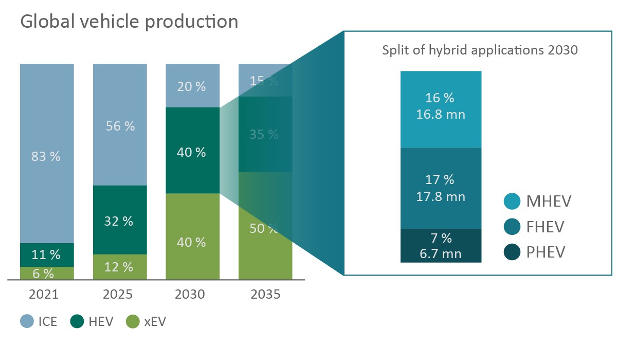
The role the plug-in hybrid drive will play will depend on the relevant regional legislation. A plug-in hybrid offers a good cost/benefit ratio, particularly where a significant proportion of a journey can be completed under electric power. To meet this requirement, the expectation is that plug-in hybrid vehicles will have to offer a range of at least 100 km in the future. Plug-in hybrid vehicles also allow drivers to cover much greater distances without having to rely on a charging infrastructure due to the option of using the ICE. In some regions of the world, this may be the drive of choice as costs continue to fall.
Schaeffler offers a range of drive systems to accommodate the many different requirements of hybrid vehicles, Figure 2.
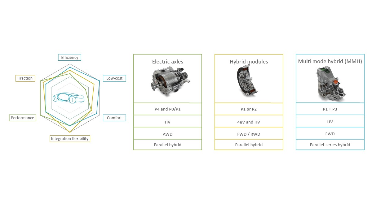
Electric axle drives in a P4 position on the rear axle allow all-wheel hybridization when combined with a P0/P1 front end topology. This specifically produces performance and traction improvements in addition to efficiency gains. Volume production began at Schaeffler in 2019: The existing set of technologies [3] forms the basis of many different solutions which are being developed further, primarily in terms of greater performance density with simultaneously fewer demands on resources. There will also be other driving characteristics for customers such as the option to influence the transverse dynamics through torque vectoring functions. Decoupling the electric axle, which allows high-efficiency all-wheel drive, is also part of the range of solutions.
Schaeffler has been producing high-voltage hybrid modules for installation between the engine and the transmission (P1 or P2, Figure 3) since 2018. A third generation module with integral converter has been in volume production since 2019 [4]. This module can be used with in-line powertrains in combination with automatic transmissions. It transmits up to 700 Nm of torque from the ICE and also supplies 300 Nm from the electric motor. This results in very high traction which is why this module is primarily used in SUVs and pick-ups. In addition to this, a fourth generation 48 V P2 drive with integral power electronics is also in development and will go into volume production in 2025. The extremely compact design, which includes the electric motor and a torque converter, allows it to be installed in a front-transverse powertrain. Direct connection to the power electronics ensures the vehicle manufacturer can integrate the system with minimal effort.
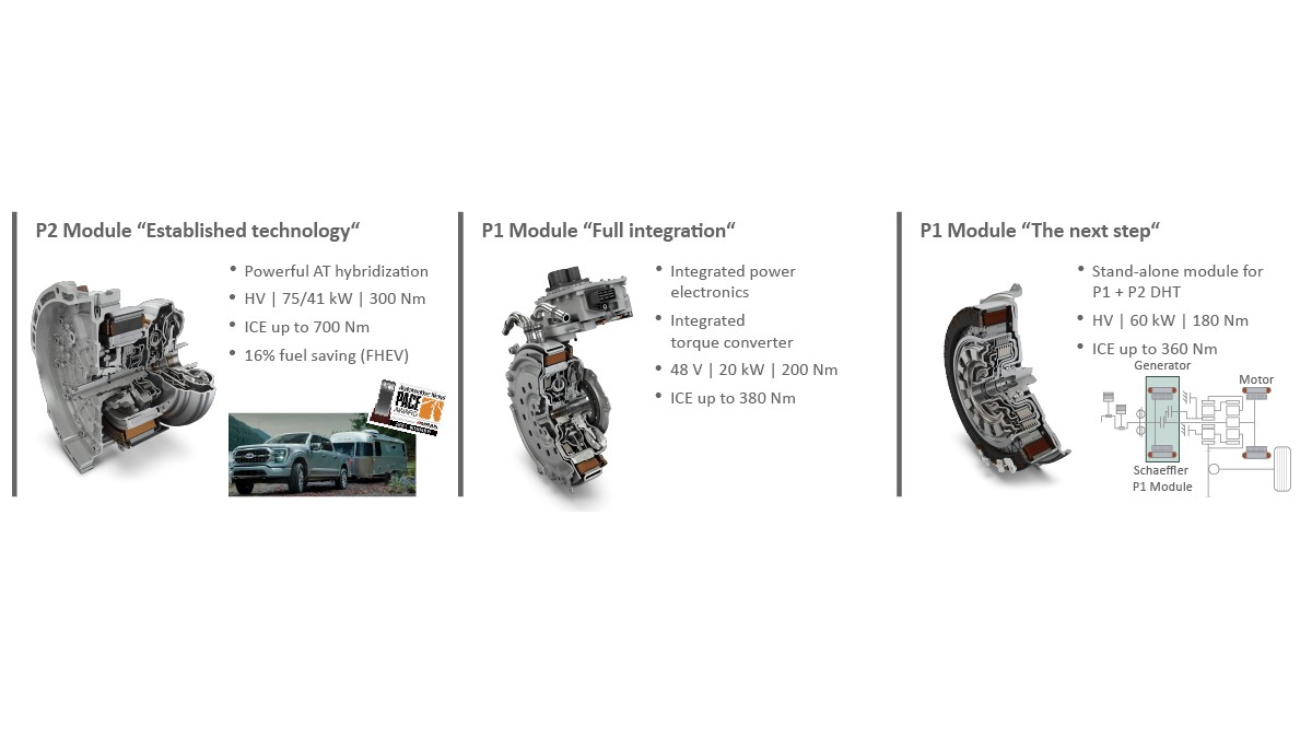
A further solution, which has been in volume production since the beginning of 2022, is a P1 hybrid module for a dedicated P1+P3 hybrid transmission. The hybrid module acts as a unit which can be tested separately for the generating P1 component of the dedicated hybrid transmission. A separating clutch is integrated within the rotor to decouple the ICE and the P1 generator during purely electric driving. As this is a three-speed hybrid transmission in the current volume application, a second clutch acts as a classic clutch. This module is 92 mm long with a 60 kW electric output and is characterized by an extremely compact axial design and a high-efficiency electric motor.
Hybrid modules offer the benefit of flexible use within an existing aggregate platform as well as very high axle torques which can be produced by combining the ICE and electric motor with the transmission ratios. Hybrid modules can basically be combined with all types of transmission. Advanced and scaled hybrid modules are now being used increasingly frequently in the electrification of commercial vehicles [6].
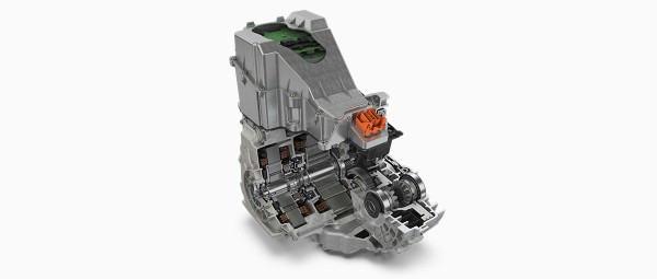
Schaeffler is currently developing an ideal, dedicated transmission for hybrid vehicles, known as a MultiMode hybrid transmission (MMH), for volume production in 2025. It has two electric motors, one in a P1 arrangement and the other in a P3 arrangement. The chosen architecture allows electric, serial, and parallel operation with direct mechanical drive by the ICE (hence, MultiMode hybrid transmission); this solution is a further step towards full electrification and includes extremely high efficiency potentials with maximum comfort and very low costs.
Design of the dedicated hybrid transmission
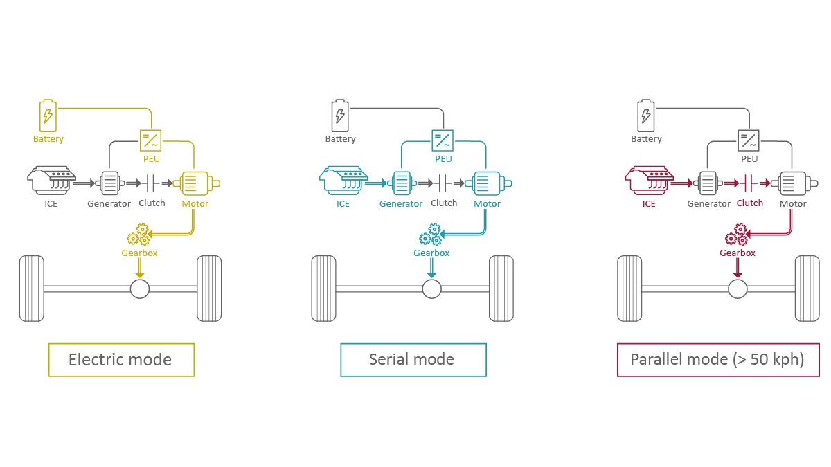
The basic architecture of the dedicated hybrid transmission developed by Schaeffler is shown in Figure 4. The construction with two electric motors, one clutch, and a fixed, non-shifting ratio has been chosen to allow both purely electric operation and serial or parallel mode. In purely electric or in serial mode, the drive is entirely via the traction motor in the P3 position. In serial mode, the ICE with the generator in the P1 position provides the required energy and can produce sweet spot operation via an additional load on the generator if required. The clutch is closed in parallel mode to facilitate direct mechanical drive via the ICE. The electric motors can also be used as an additional drive (boost) or as a generator mode (load point shifting).
The transmission is designed as a complete unit which includes all the electrical, electronic, and mechanical components, including the components required for heat dissipation, Figure 5.
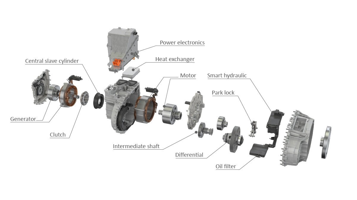
Both the electric motors with hairpin technology [7] and the central separating clutch are incorporated in a housing component in a space-saving arrangement. The transmission housing component is located behind an intermediate wall which hides all the gear stages – on the one hand a ring gear stage as a ratio between the ICE and the generator, and on the other the reduction to the axle which is achieved via an intermediate shaft in the direction of the final drive. This highly integrated solution includes the entire hydraulic unit which is controlled by the demand and which is responsible for cooling and lubrication as well as actuating the clutch and the parking lock. As a reversing hydraulic pump is used which can change conveying direction in less than 30 ms, a second pump is not required with the aid of appropriate valve logic [8].
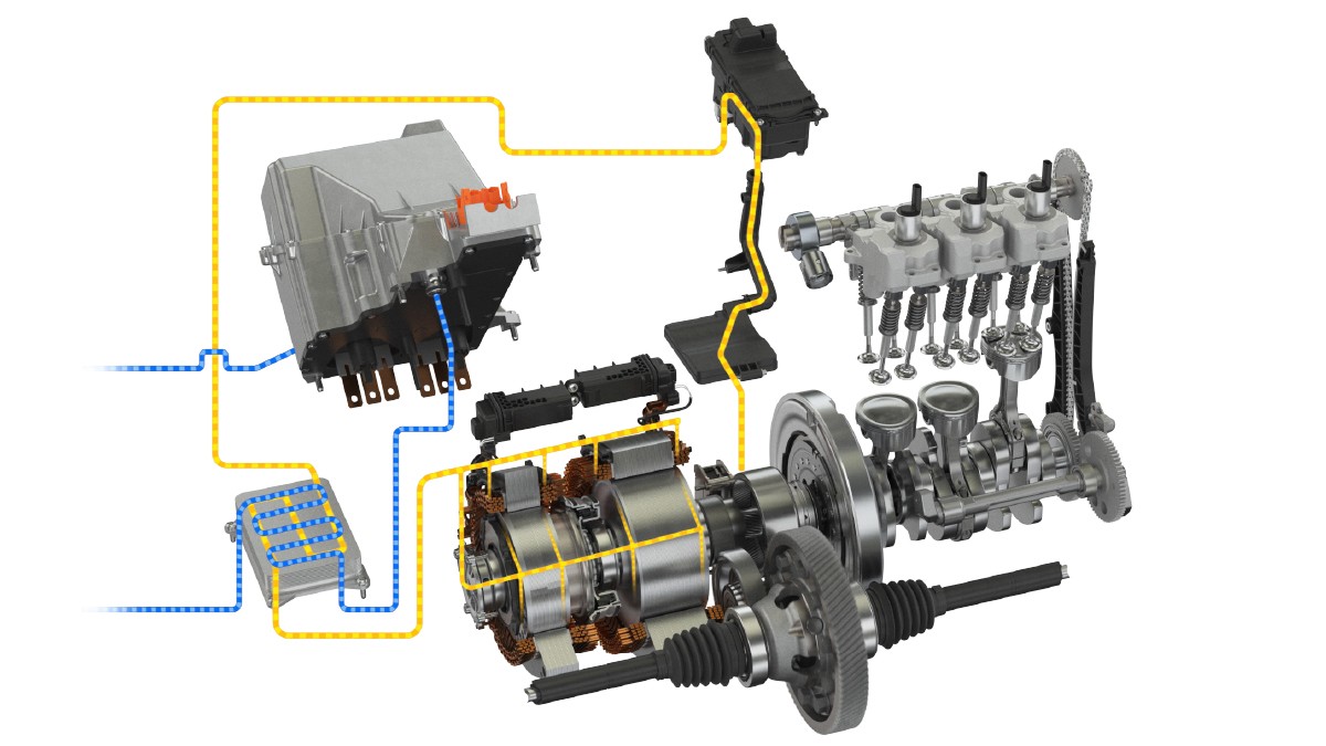
The power electronics are connected to the housing and are directly connected to the electric motors via internally arranged busbars so that no cabling is required. A water/oil heat exchanger is also located in the housing. The high degree of integration in the Schaeffler hybrid transmission allows a stepped cooling concept to be used, Figure 6, in which the vehicle's low temperature circuit acts as the external interface. The coolant flows through the power electronics and then the heat exchanger where it extracts heat from the hybrid transmission oil. The oil is then conveyed by the hydraulic unit through an oil filter in the direction of the electric motors, gearing, and bearings in a closed circuit. The hybrid transmission is designed to achieve peak power with a coolant volume flow of 8 l/min at a maximum temperature of 65 °C.
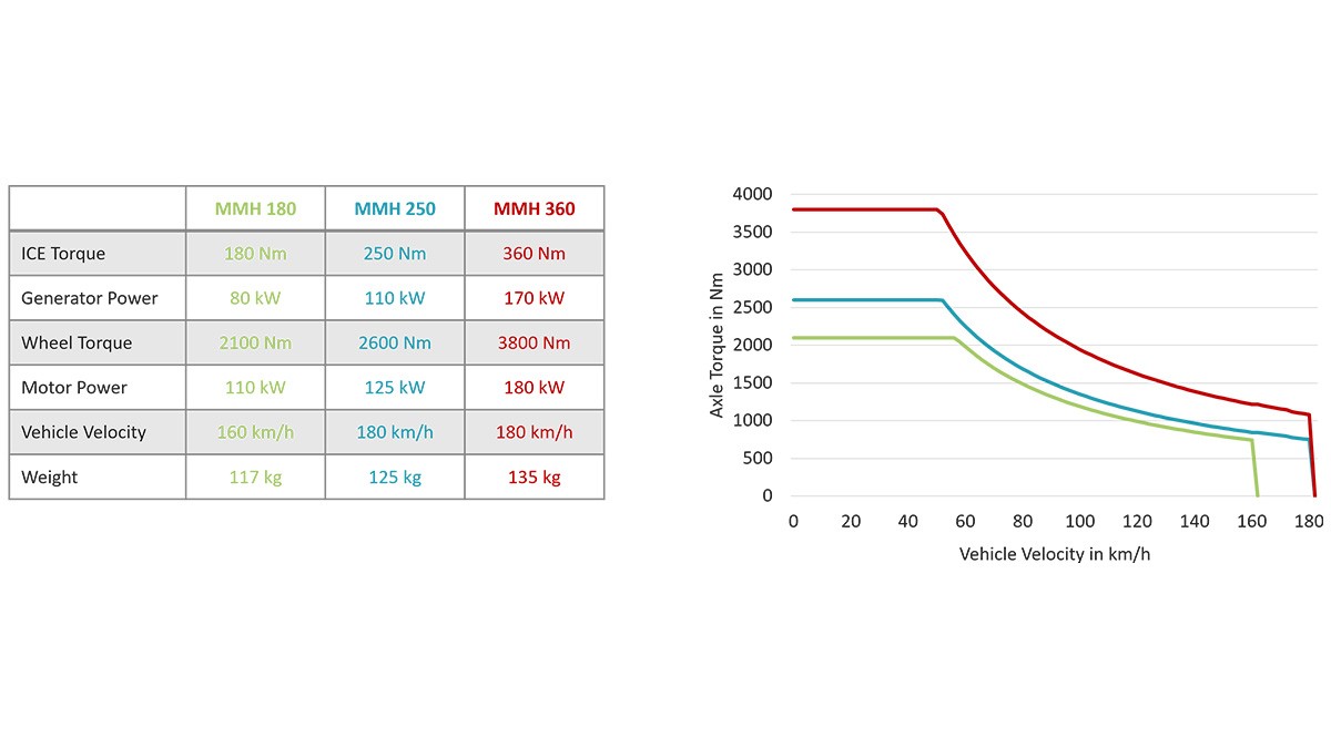
The mechanical complexity of the transmission is exceptionally low with only three running gearings and eleven bearings. The basic design is for use in front-transverse applications as a full hybrid and plug-in hybrid design. It is based on an initial electrical output of 125 kW and produces a maximum axle torque of 2600 Nm. The generator has a maximum output of 110 kW and can support torques from the ICE of up to 250 Nm on the crank shaft. The maximum speeds achieved correspond to a vehicle speed of 180 km/h. There are further plans to offer the transmission in two more torque/power classes. The decisive factor is the maximum torque of the ICE as this has a definitive influence on the operating limits of the entire drive, Figure 7. 80 to 170 kW ICEs with torques from 180 to 360 Nm can be used. The current maximum rotational speed of the internal combustion engine is 4,700 rpm which corresponds to a modern turbocharged gasoline engine. The outputs of both electric motors are primarily adapted to the requirements by varying the active length.
Function of the hybrid transmission
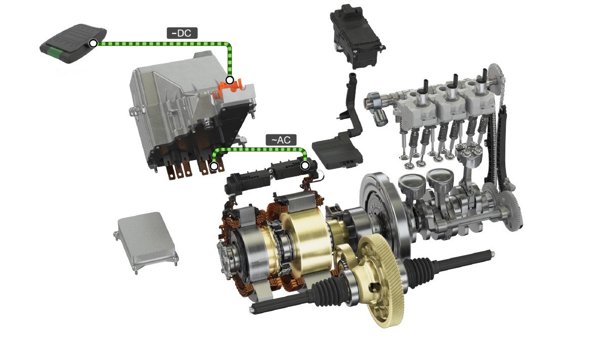
The various operating modes are shown below based on a notional journey with a full hybrid variant of the transmission. Before setting off, the hydraulics release the parking lock with a pressure of approximately 6 bar. To achieve this, both a ‘normally closed’ status and a bistable lock can be realized. Acceleration from stationary is purely electric via the P3 traction motor with an open clutch and the corresponding level of battery charge, Figure 8. The rotational speed of the electric motor is transmitted to the drive axle via an intermediate shaft and the final drive at approximately i = 8.3 and thus provides the same driving experience as a battery-driven electric vehicle.
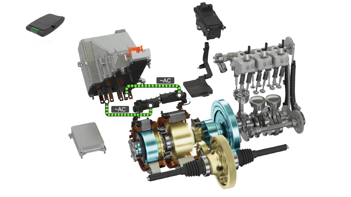
The ICE is started via the electric motor generator for further acceleration to a typical out-of-town speed and as more energy is required. In the subsequent serial mode, the generator produces a current which is converted directly to mechanical energy in the second electric motor, i.e. without any detour via battery storage, Figure 9. The direct transmission of current via a secondary circuit instead of charging and discharging the battery ensures, on the one hand, greater efficiency, and, on the other, lower costs as lower capacity battery cells with lower service life requirements can be used.
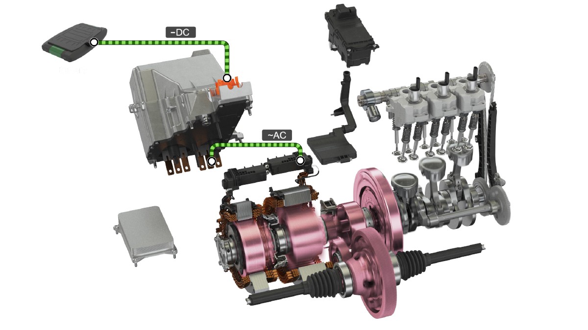
As soon as cruising speed is achieved, the optimum overall efficiency level can be achieved by shifting to parallel mode. Closing the lamellar clutch allows the ICE’s torque to be used to drive the wheels directly, Figure 10, and the electric motors can produce current for the vehicle’s electric system or additional torque for the drive. Closing the clutch and therefore shifting to parallel mode is completed hydraulically within less than 200 ms after synchronizing the speeds of the electric motors.
Recuperation takes place during braking via the electric motor in the P3 position with the clutch open. The design of the integral DC/DC converter for the full hybrid variants with a nominal output of 44 kW (for 20 sec) provides corresponding braking performance which allows all the delays from the cycle to be completely recuperated has come to a standstill.
Operating strategies and drivability
The overall efficiency of a hybrid drive and thus the level of CO2 reduction is driven by not only the individual components but essentially by the way they work together and therefore the operating strategy. The following operating strategies for both a full hybrid and a plug-in hybrid variant are shown using the example of an MMH which allows the fuel consumption to be optimized in the WLTC charge sustaining mode. The difference at the vehicle level primarily lies in the size of the battery which has a significant impact on the driving strategy.
In a full hybrid vehicle, only a small battery is available so a ‘power depending’ strategy is used, Figure 11. In serial mode, the speed is always selected from the ICE, irrespective of the wheel speed, which provides the optimum specific consumption point as a function of the power requirement. In parallel mode, the driving speed determines the target output at a corresponding rotational speed. Overall, this results in a comparably larger working range for the ICE.
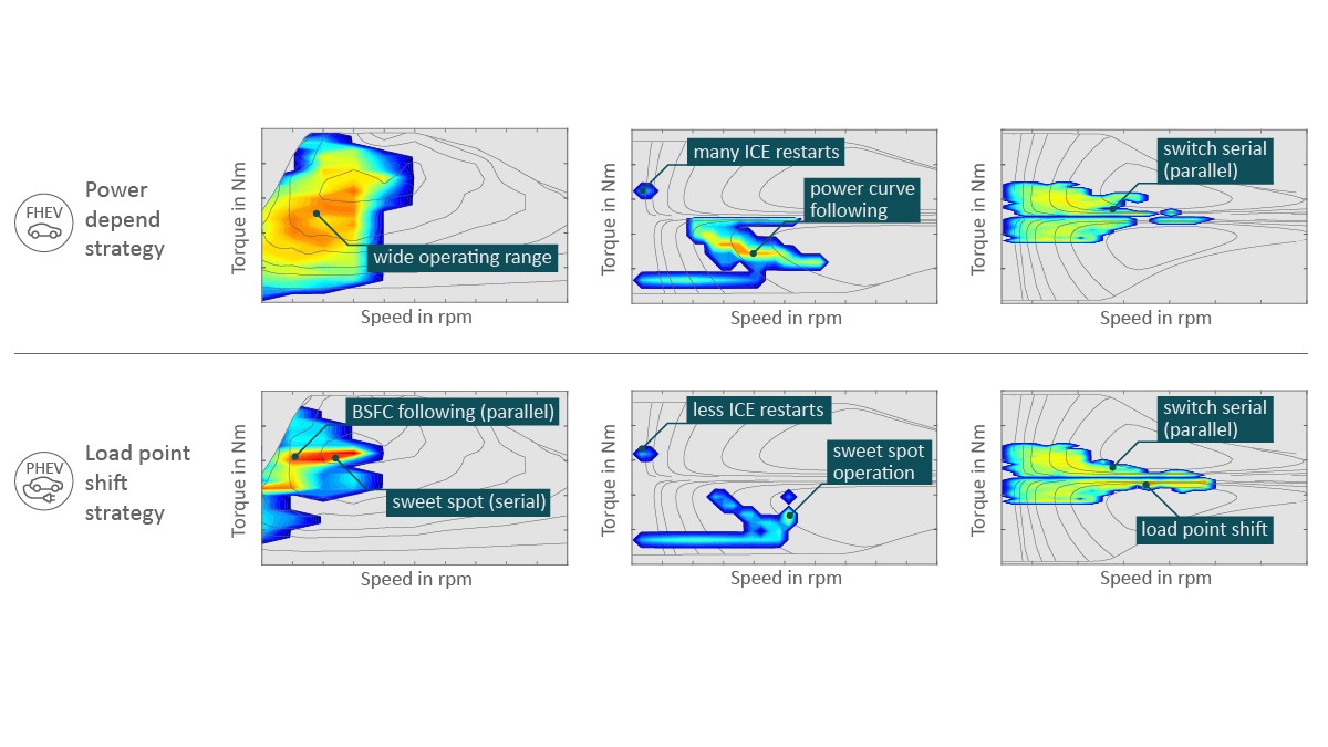
When operating as a plug-in hybrid vehicle with a significantly larger battery, it is expedient to operate the system with load point shifting. In serial mode, the ICE is operated in the best specific consumption point in the engine performance map. In parallel mode, the load is selected such that the speed-dependent operating point is on the optimum specific consumption curve and excess energy is saved back to the battery while missing energy is provided by the battery. How the ICE is specifically optimized in this context for a serial/parallel hybrid drive is described in [8].
The generator performance map in Figure 11 shows the corresponding mode along a performance curve for the full hybrid drive. The sweet spot for a plug-in hybrid is clearly in serial mode. The frequency with which the ICE has to be restarted decreases as the size of the battery increases. The horizontal line in the generating quadrant shows, in both cases, that the kinetic energy of the ICE is consistently recovered in generator mode when turned off.
The performance maps for the traction motors show that between 4000 rpm and 6000 rpm, there is a transition from serial to parallel mode as the degree of utilization decreases considerably from here. In the plug-in hybrid, the generating quadrant exhibits much greater utilization at low loads due to load point shifting implementation. The utilization range can change depending on the system to provide up to 100 % coverage of the driving in a range-extender vehicle.
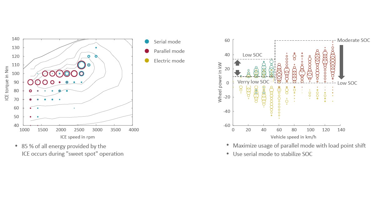
It was possible to illustrate the potential of the MultiMode hybrid transmission using a demonstration vehicle. A current volume-produced vehicle was converted using a plug-in hybrid drive (1.6 l gasoline engine with nominal 80 kW power, front-transverse installation, double clutch transmission, P2 electric motor). Consistent load point shifting in the demonstration vehicle in parallel and serial modes ensures that more than 85 % of the operating points in the WLTC (trickle charge mode) are in the area of the optimum specific fuel consumption, Figure 12 (left). Figure 12 (right) shows the various driving modes over driving performance and vehicle speed. Starting with a high battery charge status, the transition initially shifts from parallel to electric mode for lower driving performance and then the transition moves from serial to electric mode. If the battery charge status reaches a low level, as shown in Figure 12 (right) the electric and parallel operating areas are maximized for efficiency reasons whereas the serial component is used primarily to stabilize the battery charge status. From approximately 60 km/h, the primary mode is parallel.
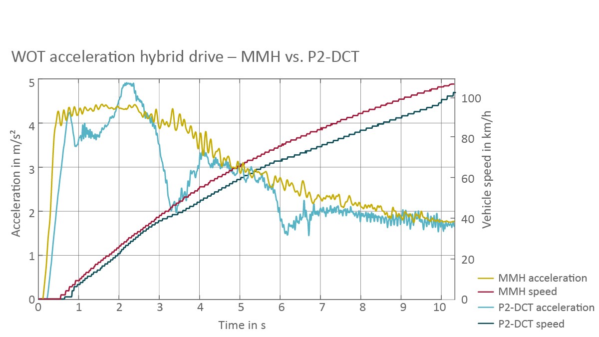
It is equally important that the operating strategy is designed such that very good drivability is achieved. Figure 13 uses the full load acceleration measured on the demonstrator vehicle to show that the Schaeffler dedicated hybrid transmission not only achieved a faster speed more quickly over the time interval in question than the P2 hybrid transmission installed as standard, but that the longitudinal acceleration is more even as there are no torque breaks due to shifting. The Schaeffler hybrid drive can achieve a hybrid full load acceleration of 0 to 100 km/h in 9.2 s while the volume-produced vehicle with the same battery and identical ICE requires 10.4 s. In addition to this, this vehicle drives as comfortably as an electric vehicle due to the even acceleration characteristics and therefore already exhibits electric ‘DNA’.
In addition to this, it is clear that the vehicle interfaces are also very easy to operate when using the MultiMode hybrid transmission. There is a torque interface for communicating with the vehicle and a status interface for the clutch and the parking lock, i.e. only the status (open or closed) has to be controlled. The effort required to calibrate the vehicle is also extremely low compared to classic transmissions due to its intuitive design.
Further conceptual development
Schaeffler is continuing to explore further optimization opportunities over and above the current volume development of MultiMode hybrid transmissions. One objective is to reduce further the space requirement and costs as well as to increase the efficiency and performance density.
One evolutionary option to reduce further the overall complexity and the system costs is to use a shiftable sliding sleeve instead of a lamellar clutch. The actuation of the sleeve and the parking lock can be either hydraulic or electromechanical. This can be combined with an entirely water cooled arrangement for the electric motors and passive oil lubrication of the mechanical elements. This design also dispenses with the ratio stage between the ICE and the generator which allows mechanical losses to be reduced further. In addition to this, losses when decoupling the engine in parallel mode can be reduced with a second sliding sleeve.
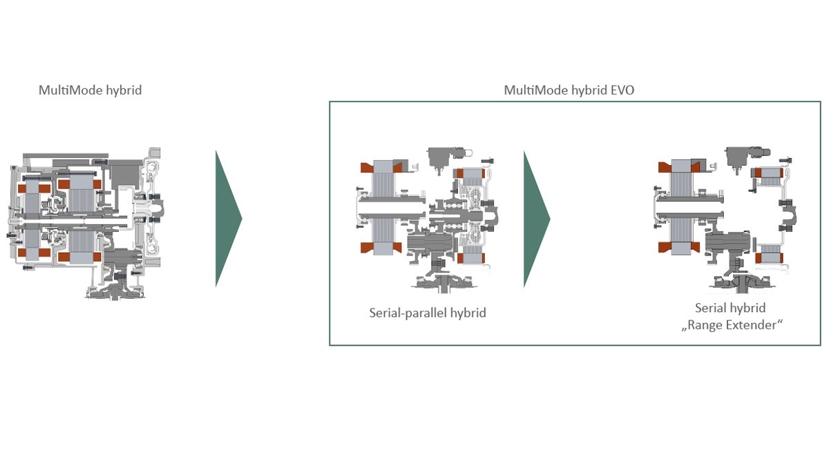
The real space and cost benefits of this solution-based approach are leveraged if a more radical approach is taken to the concept and only the serial mode is implemented, Figure 14. In this case, only the electric motor driven by the generator is connected to the crankshaft to form a ‘range extender’ together with the ICE. The electric traction motor, on the other hand, forms an electric axle with a spur gear stage and differential. In this case, the coupling is purely electric via the power electronics.
The achievable cost savings with this type of concept are based on the fact there are fewer components. On the one hand, there is no need for the damper as there is no direct drive from the ICE to the wheel which affects comfort. On the other, the separating element and its actuation are also not required as there is no need for a mechanical coupling. Furthermore, in this type of application, the ICE can be designed to operate in a specific map area only, with minimal specific fuel consumption. This type of concept is particularly interesting for markets in which higher speeds (where the efficiency benefits of direct drive can be exploited) are not relevant due to the corresponding driving cycles and where there are also certain price sensitivities.
A revolutionary, innovative modification to the dedicated hybrid transmission is the combination of two electric motors in a stator where the radially internal component of the stator (internal rotor) acts as the generator and the radially external component (external rotor) as the motor, Figure 15. The benefit of this nested design is its high performance density. In addition to this, there is a significant reduction in the material used as both motors can be punched out of sheet steel. The central stator yoke can be used by the magnetic fields of both machines.
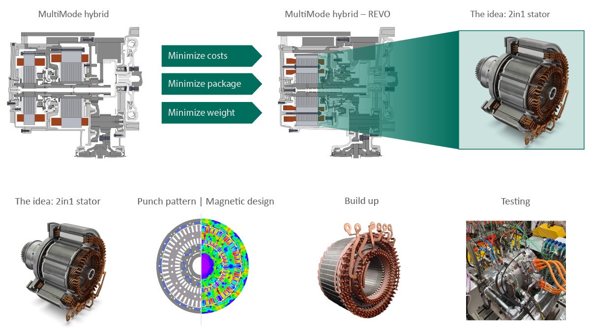
Possible reciprocal effects from the magnetic fields between the two motors represent a challenge here. Initial measurements on a prototype indicate that the reciprocal effects of the magnetic fields are minimal and can be regarded as manageable. When integrated into the Schaeffler hybrid transmission, a weight reduction of 10 kg and a length reduction of 49 mm can be achieved. The rigidity of the powertrain also increases while the costs decrease. This design of motor is basically suitable for all hybrid transmissions based on two electric motors.
Summary
Hybrid drives which provide a high percentage of electric driving are making an important contribution to the reduction of CO2 emissions in the transport sector and, combined with synthetic fuels, would even be one way to contribute to complete CO2-neutral road traffic in the future – particularly in areas of the world where there is currently insufficient charging infrastructure. For this reason, Schaeffler is expanding its current portfolio of electric axle drives and hybrid modules to include a dedicated hybrid transmission which facilitates both serial and parallel electric drive and ICE modes and is therefore also known as the ‘MultiMode hybrid transmission’ (MHH). This dedicated hybrid drive can be utilized in both full hybrid and plug-in hybrid vehicles and can therefore be adapted to the regulatory and infrastructure requirements in different parts of the world.
The design with two electric motors, one clutch, and a fixed, non-shifting ratio has been chosen to allow three possible operating modes: Purely electric driving using the charge stored in the battery, electric driving with the ICE running to produce the energy required, and direct mechanical drive by the ICE for load points where this is a particularly effective solution.
The mechanical complexity of the hybrid transmission is exceptionally low with eleven bearing points, a ring gear stage, and two spur gear sets. The hydraulics, with their single pump concept, also have a favorable cost/benefit ratio. As there is no shifting, the application effort is minimal which means significant consumption improvements can be achieved by consistent implementation of the operating strategy.
In building a demonstration vehicle, Schaeffler is corroborating both the fuel consumption potential and excellent drivability which is very close to that of a vehicle with purely battery-driven electric drive in terms of acceleration behavior and driving comfort. In this respect, the hybrid transmission for passenger vehicles represents a decisive step in the further development of hybrid drives towards an increasingly electric future. Schaeffler is extending current volume-based developments by working on both an even more compact design using a nested construction for the electric motors and a further simplification of the entire concept to a pure ‘range extender’.
1] European Commission (pub.): Proposal for a regulation of the European Parliament and of the Council amending regulation (EU) 2019/631. COM (2021) 556 final
[2] Executive Department State of California (pub.): Executive Order N-79-20
[3] Biermann, T.: The Innovative Schaeffler Modular E-Axle. Baden-Baden: Schaeffler Kolloquium, 2018
[4] Reitz, D. et al.: P2 High-Voltage Drives: Efficient Hybridization for all Transmissions. Baden-Baden: Schaeffler Kolloquium, 2018
[5] Elicker, M.; Knorr, M.; Möller, A.: Commercial Vehicle Drives of the Future. Bühl: Schaeffler Kolloquium, 2022
[6] Pfund, T.: Efficient Scale-Up to Volume Production of Innovative Electric Motors and Power Electronics. Bühl: Schaeffler Kolloquium, 2022
[7] Göckler, M.; Biegert, P.; Grethel, M.: Next-generation Actuator Systems. Baden-Baden: Schaeffler Kolloquium, 2022
[8] Strauss, A. et al.: The Final Stage in the Evolution of the Internal Combustion Engine in Hybrid Powertrains. Bühl: Schaeffler Kolloquium, 2022