Commercial Vehicle Drives of the Future
Michael Elicker l Michael Knorr | Andreas Möller
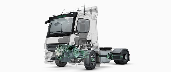
Heavy commercial vehicles are responsible for 40% of all CO2 road traffic emissions in Europe. Against this backdrop, engine manufacturers are working at full stretch on climate-friendly solutions. The avenues explored in this quest are as diverse as the applications: Particularly fuel-efficient combustion engines, which are being operated to an increasing degree with hydrogen or synthetic fuels, are as much a part of the future as hybrid drives. Fully electrified commercial vehicles, which store the driving current in a battery, or generate the current on board by fuel cell, are rapidly gaining market share. Schaeffler is supporting all of these potential solutions with innovative technologies, which are proving advantageous in terms of increased electric range or lower fuel consumption.
Minimum quantity, maximum effect
Although discussions on future transport are dominated by individual personal mobility, the movement of goods also has a key role to play, not only in the functioning of a developed economy but also with a view to climate protection. Despite the fact that there are 277.8 million registered cars in the European Union (including Great Britain) and only 6.8 million trucks with a maximum permissible weight of more than 12 t, the distance traveled by an average commercial vehicle is considerably higher than that of a car. As a result of the distances traveled and higher vehicle mass, the quota of CO2 emissions generated by trucks among road users is disproportionately high at around 40%. The relatively rapid renewal of fleets within thirteen years essentially provides a starting point for the introduction of ground-breaking, climate-friendly technologies, provided that these improve or, at the very least, have no detrimental effect on the “Total Cost of Ownership” (TCO) for the operator of the commercial vehicle. From Schaeffler's perspective, these initial conditions justify the development of solutions, which are specific to commercial vehicles, in carving the path toward climate-neutral mobility.
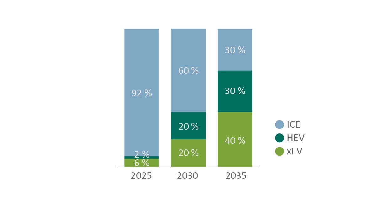
Not only in Europe, but also in other leading markets of the commercial vehicle industry such as America, China, or India, greenhouse gas emissions will be subject to increasingly stricter regulations in the years running up to 2030 - and will include the addition of new exhaust pollutants. Overall, there is a high demand for innovation in the field of powertrains, which is being satisfied by various technical approaches. Conclusions drawn from market analyses conducted by Schaeffler show that alternative drives will gain significant market share in the coming years, Figure 1. In 2030, electric vehicles with and without fuel cells (xEV) will achieve a global market share of around 20%, and a further 20% will be equipped with a hybrid drive (HEV). In 2035, the xEV quota will have already reached around 40% and hybrid drives will have achieved a further market share of 30%. Conversely, this also means around 60% of all newly registered commercial vehicles will still be equipped with an internal combustion engine (ICE) in 2035.
Schaeffler offers innovative technologies for all drive concepts, which either significantly reduce vehicle-specific CO2 emissions or pave the way for completely CO2-neutral goods traffic.
Efficiency for all drives
Avoiding power loss plays a key role at all times, regardless of the drive concept. In fully electrified drives, a lower frictional power leads to a higher range with an identical battery or an identical range with a smaller battery, resulting in lower acquisition and operating costs for the fleet owner. In conventional drives, fuel consumption is reduced, with resulting reductions in both the vehicle's CO2 emissions and operating costs.
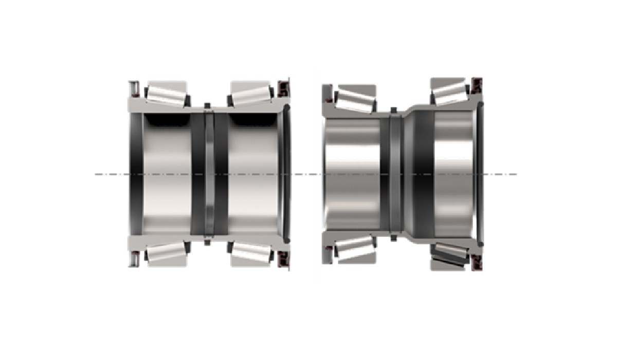
An example of the considerable and ever prevalent potential for reducing frictional power is demonstrated by the wheel bearing units developed for use in commercial vehicles. Like their counterparts from the passenger car sector, these are based on two single-row tapered roller bearings, which are combined to form one unit. Tapered roller bearings are used in wheel bearings due to the ability of this rolling element shape to absorb forces occurring in both a radial and an axial direction. As axial forces are absorbed on a directional basis, two tapered roller bearings must always be mounted in opposing directions as an inner and outer wheel bearing. In order to achieve a further, consistent reduction in friction, Schaeffler has developed a wheel bearing unit in which both bearings are connected via a stepped inner ring and a shared housing, Figure 2. The low friction is achieved, for example, through the use of appropriate coatings on the rolling elements and raceways, and adaptation of the sealing concept. The lubrication of the sealed unit is designed for the service life of a traction unit used in long-distance transport (1.6 mill. km).
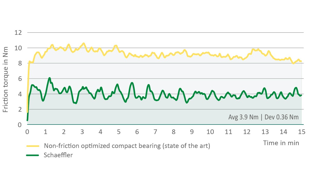
Measurements were carried out using a specially developed test setup, in which a driven rear axle with a maximum axle load of 13 t was operated at a constant wheel speed of around 500 rpm (corresponding to around 90 km/h). After replacing a conventional bearing solution composed of two structurally independent tapered roller bearings, the new wheel bearing unit succeeded in reducing friction by 56%, Figure 3. The operating temperature measured at the bearing positions was around 16% lower, which is not only a clear indicator of the lower frictional torque in rolling contact, but also increases the life of the grease used for lubrication.
The energy saving achieved through the use of the wheel bearing units is up to 600 W per 13 t axle load. For a commercial vehicle with an electric range of 500 km, this results in an energy saving of 11 kWh (incl. final drive) per charging process. If the battery capacity is reduced accordingly, the resulting cost saving is approx. 1,100 euros. A weight saving of up to 30 kg per driven axle can also be applied depending on the specific design. If we also factor in the reduced weight resulting from the smaller battery, the payload of the vehicle increases by 96 kg. As several assembly steps can be omitted compared with the use of individual bearings, the wheel bearing unit is not only advantageous for the vehicle operator but also for the vehicle manufacturer.
Tire air pressure is an aspect that is often overlooked in connection with driving resistance. Deviations from the target value can lead to increased tire wear and a considerable increase in driving current or fuel consumption. Schaeffler has developed a wheel bearing unit with a pneumatic rotary union to the tire, to simplify adjustment of the air pressure, Figure 4.
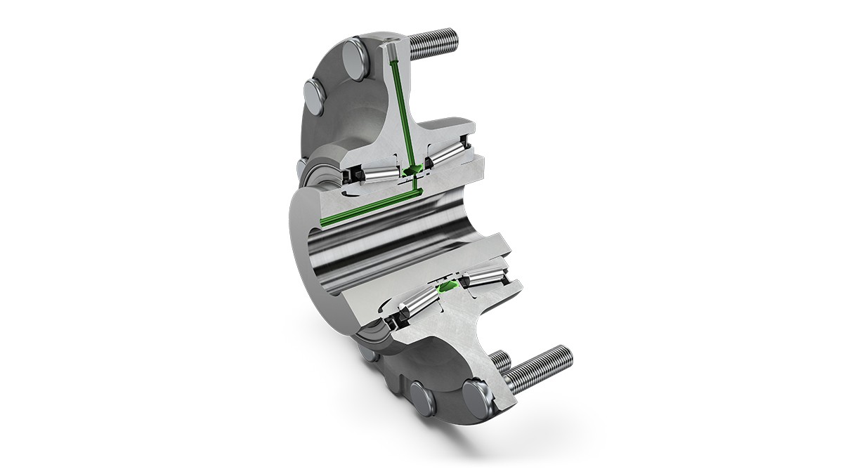
The added value of the air charging system is demonstrated in off-highway applications, where drivers specifically reduce the tire pressure on unpaved surfaces in order to improve off-road traction. The tires have to be reinflated for use back on paved surfaces. The wheel bearing system with integrated inflation function will also allow these adjustments to be performed automatically in future. As a result of this innovative approach, the size and number of external and thus damage-prone pressure hoses, such as those encountered in currently established systems, can be reduced.
Variability for internal combustion engines
Commercial vehicles, which are still powered by internal combustion engines during or after 2030, will be subject to significantly stricter limits for both CO2 and pollutant emissions. An increasing quota of the fleet will be driven by hydrogen or synthetic fuels, which, in some cases, will necessitate a conversion from the diesel engine combustion method that has been prevalent to date, to a gasoline engine process [1]. Uncertainties surrounding the global availability of alternative fuels support the use of systems that are not only compatible with the various fuels currently used but also with future combustion processes. In terms of the valve train, this enables adaptation to engines with both compression ignition and spark ignition without changing the basic engine. An engine braking function with a high power density can also be achieved.
In order to meet these requirements, Schaeffler is developing two systems for a variable valve train which are specific to commercial vehicles. The first of these systems is the electrohydraulic fully variable valve train system, which has been in volume production for passenger cars since 2009, and is now undergoing further development for commercial vehicle applications. The second is a completely new and discretely switchable electromechanical system designed exclusively for commercial vehicles. Both approaches are described below.
Electrohydraulic fully variable valve train for commercial vehicles
The electrohydraulic valve train system “UniAir” [2], which has been successful in the passenger car segment, is undergoing further development under the name “iFlexAir System” for use in commercial vehicles. In order to be able to guarantee the high functional safety aspects and actuating forces in the commercial vehicle engine, a structure is being used, Figure 5, which provides a dedicated oil circuit for each valve, whereby the valves are supplied via a dual-action axial piston pump. Two pistons are actuated by means of a camshaft, but form a structural unit in which one piston is located inside the other piston, which in turn is designed as a hollow cylinder.
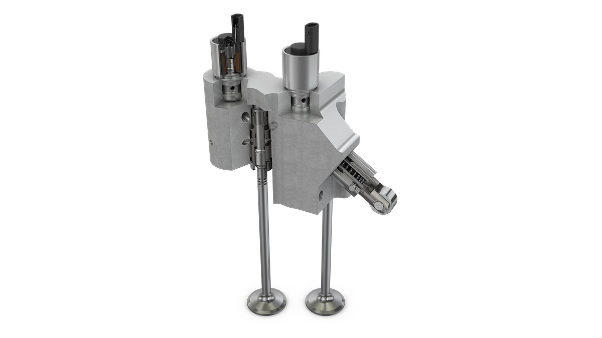
As the stroke for each valve can be freely selected between zero and full stroke, the stroke curve is not geometrically determined in such a system. The only limiting factor is the hydraulic inertia of the system. In broad ranges, however, the stroke curves are determined solely by the software, which creates additional variability, as different engine topologies can be operated with one system. This also permits the implementation of new functions, for example by generating a charge movement in the cylinder through varying opening times and valve strokes of adjacent intake valves. The rapid reaction of the air path to transient motor operation made possible by the iFlexAir System is a major advantage, particularly in spark-ignition engines with ignition timing shift, and is reflected in fuel consumption and emissions. The system also supports high-efficiency engines, as the fully variable valve train permits an increase in the geometric compression ratio.
A significant advantage of the electrohydraulic valve train in commercial vehicles is the already integrated hydraulic valve lash adjustment, which reduces maintenance costs for the operator. In contrast to modern passenger cars, valve lash adjustment in many commercial vehicle engines is still carried out as a mechanical adjustment at fixed intervals in automotive workshops.
Although the application effort associated with an electrohydraulic valve train is, by no means, negligible, Schaeffler can also draw here on more than ten years’ experience in the passenger car sector and has the relevant know-how and application algorithms to reduce the additional outlay. The iFlexAir System therefore offers maximum flexibility and future viability.
Valve train for commercial vehicles with discrete, electromechanical switching action
For some applications, discrete switching – or the opening and closing of valves independently of camshaft position – is sufficient and, to this end, volume production of the electromechanically actuated eRocker system will start in the passenger car sector in 2022 [3]. A completely new system based on the principle of a switchable valve bridge is now in pre-development for use in the engines of commercial vehicles. Due to the use of electromechanical actuators, there is no need for the hydraulic circuit that is required for the iFlexAir System. As a result, the installation space required in the cylinder head is so small that existing engine series can be converted as part of a modularization strategy.
The basic idea of the valve bridge is not to prevent the mechanical movement of the rocker arm, but rather to enable an idle stroke, despite actuation of the lever, Figure 6, in which the valve spring keeps the valve closed. The dead space required for this is created by moving a metal plate, known as a shim, which is attached to the bridge with the ability to move. In the configuration shown here, an electrically controllable actuator is used for each valve, which allows the shim to move laterally on the bridge by means of a deflecting lever mechanism. The shift fork used for this purpose is designed in such a way that any vibrations and distortions occurring during engine operation do not impact on the reliability of the system.
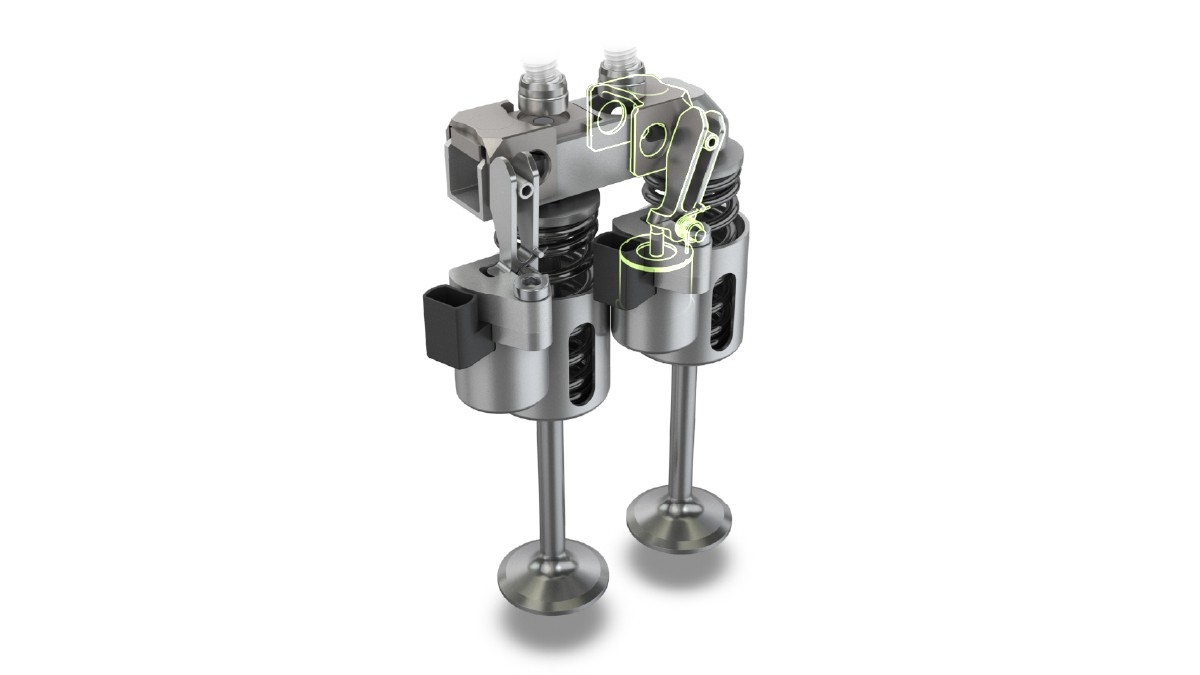
At a maximum of 13.9 N, the required actuating forces for this system are very low, thus permitting the use of compact actuators with current diameter and height dimensions of 25 mm and 30 mm respectively. During the switching process, which is completed within a maximum of 30 ms, a current of 2.5 A per actuator must be present for a 24-volt on-board power supply. For the subsequent actuation state, a continuous current of only 0.3 A per actuator is required, with the result that the electrical power requirement can be minimized.
As an innovative solution, the switchable bridge offers a range of advantages, the most important of which include:
- Minimum installation space requirement: This allows the system to be adapted to engines with a bottom camshaft, for example.
- Flexible system configuration: Scaling is possible from pure cylinder deactivation and individual valve actuation through to full functionality on both valves and on both the intake and exhaust side.
- Adaptation of modern and ground-breaking engine brake function.
- Simple mechanics with high expectations in terms of service life: If the system fails, full valve lift is maintained, so that the engine remains operational.
- Electromechanical actuation: Extremely rapid switching times can be achieved irrespective of temperature.
Ongoing tests are primarily aimed at quantifying the emission and fuel consumption advantages that can be achieved with the system. This involves verifying the entire usable mapping range, including early valve closing times in high-load operation (Miller process). Due to the future emissions legislation, the current focus is on reducing raw emissions and the rapid increase in exhaust gas temperature which occurs under low loads, so that additional components such as an electrically heated catalytic converter are not required.
Benefits of using alternative fuels
In addition to the use of paraffin fuels, which include synthetic diesel fuel manufactured using the Fischer-Tropsch process, several alternatives for commercial vehicles are being discussed, which would involve a switch to internal combustion processes with spark ignition. In particular, the direct use of hydrogen in correspondingly converted internal combustion engines is currently being tested at an international level by many vehicle and engine manufacturers. The benefits of a variable valve train system for spark ignition engines can be illustrated using a typical engine map, Figure 7.
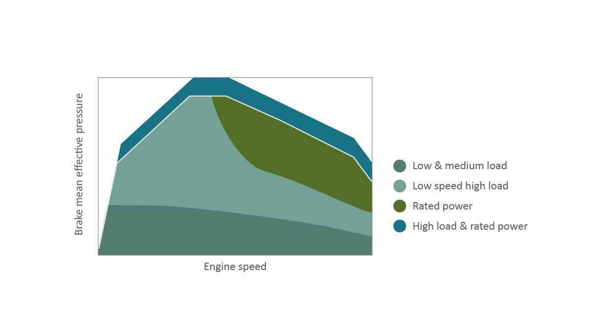
In the low load range (zone 1 in Figure 7), a variable valve train enables dethrottling or internal exhaust gas recirculation through retardation. Depending on the system, cylinder deactivation can also be achieved. At higher loads (zone 2 in Figure 7), the main aim is to extend the knock limit by closing the intake valve early and thereby increase compression and efficiency. An improvement in valve overlap as a function of the operating point can also be achieved. At high load points (zone 3 in Figure 7), avoiding full-load enrichment, which is necessary for protecting components, is particularly important in addition to avoiding knocking.
A special feature of hydrogen-based internal combustion engines is that mixture formation in the first generation will presumably be achieved by means of intake manifold injection, while later engine generations will use direct injection into the cylinder. A variable valve train system enables very precise control of the air path, regardless of the mixture formation method, and thus contributes to the future stability of new engines. The same also applies to extremely lean operation for which future hydrogen engines could be designed and which requires a very rapid adjustment of the air/fuel ratio as a function of the operating point. The following applies regardless of the fuel: Variability in the valve train creates variability in the overall engine design.
Energy management by hybrid drives
As described at the start, we are seeing a clear trend toward equipping commercial vehicles with hybrid drives. Particularly good opportunities are being attributed to mild hybrid drives with a 48-V partial on-board power supply, as their increased recuperation capacity allows an electric catalytic converter to be heated using previously harvested brake energy, for which a heavy truck temporarily requires up to 13 kW. Furthermore, the recuperated energy can also be used in acceleration processes. By shifting the load point in the combustion engine map, the manufacturer’s CO2 fleet balance can be improved with the aid of the electric motor.
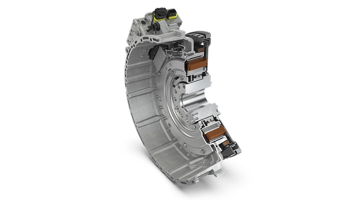
The example of a 48-V hybrid module, which is currently being developed for installation on the crankshaft (P1), shows how the know-how gained with electric drives in the passenger car segment can be applied to the commercial vehicle sector, Figure 8. This solution comprises a permanently excited, water-cooled e-machine with a continuous output of 22 kW and a maximum output of 28 kW. The maximum torque is 400 Nm. The module is designed to achieve a maximum efficiency of 96% at an engine speed, which is typical for heavy commercial vehicles, of 900 rpm.
The fuel savings that can be achieved with the hybrid module are largely dependent on the respective driving cycle and on the load. The largest saving in percentage terms is produced with a low load cycle, as is typically encountered with food distribution traffic in urban centers. In combination with an electrically heated catalytic converter for a heavy commercial vehicle, with a permissible total weight of 40 t, this saving is around 15% compared with a basic engine that meets future emission limit values, Figure 9. If the internal combustion engine is also equipped with a variable valve train system, the savings can can be 20 % and more.
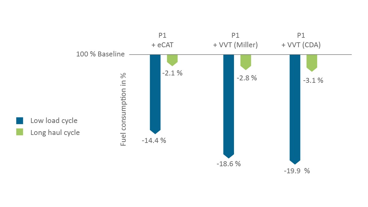
In long-distance transport (“Long Haul Cycle”), where long distances are covered at a constant speed, the percentage saving is considerably lower at 2.4% for hybridization and up to 3.2% for the combination of hybrid module and variable valve train. However, the annual mileages associated with long-distance transport are considerably higher, resulting in fuel cost savings for the operator of up to 1,600 euros per year based on current gas station prices (lower AdBlue consumption included). Hybridization is also beneficial from the manufacturer's perspective in helping to avoid the drastic penalties incurred if the CO2 fleet limits are exceeded.
High voltage for electric powertrains
Commercial vehicles that are to cover longer distances in long-haul transport by purely electrical means are reliant on ultra-rapid battery recharging or an on-board facility for generating power via a fuel cell. A voltage of up to 800 V is proving successful for the on-board drive system in enabling high charging performance among heavy commercial vehicles. In order to achieve economies of scale despite the comparatively small production volumes in the commercial vehicle industry, standardization of the drives is essential. Based on experiences with electrical axle drives for passenger cars, a standard architecture has therefore been developed for the electric commercial vehicle powertrain, which encompasses both electric motors and power electronics.
The power electronics are essential for the function and efficiency of the electric powertrain. Schaeffler is currently developing power electronics based on silicon carbide (SiC), which are tailored specifically to the requirements of commercial vehicles and designed for voltages up to 850 V and effective currents of 600 A (peak power) and 400 A (continuous power). With a volume of 12.4 l, these achieve a space-saving power density of more than 40 kW/l. All electrical and mechanical components are designed for the significantly higher mileages covered by heavy commercial vehicles. The power electronics can also be connected to the standard on-board vehicle power supply via a 24-volt direct current connection.
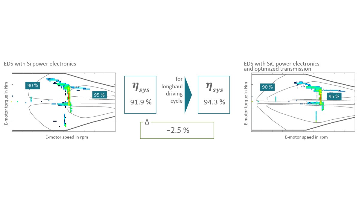
The higher switching frequencies facilitated with the aid of the silicon carbide technology and the increased cooling capacity of the power electronics components giving a high continuous output specifically for commercial vehicle use, lead to significantly improved efficiency of the electric powertrain. Simulations show that the system efficiency of the electric motor, power electronics, and axle drive is 91.9% when conventional silicon semiconductors are used in a typical commercial vehicle driving cycle. In combination with an optimized gearbox, a switch to silicon carbide semiconductors produces a system efficiency of 94.3%, Figure 10.
For a battery-electric long-distance truck designed for a charging range of 500 km, the battery capacity can be reduced by 14 kWh with this drive system, which, in turn corresponds to a weight reduction of 84 kg and a current cost saving of around 1,400 euros from the battery adaptation alone.
Expertise in fuel cell-powered trucks
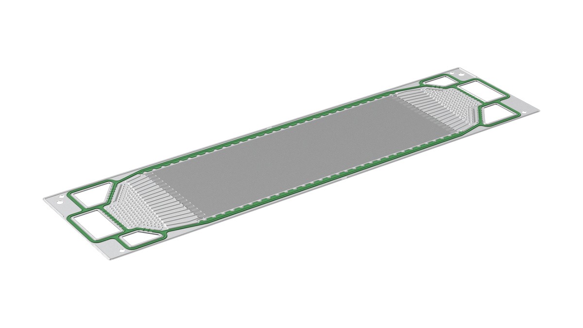
It is not currently possible to determine, with any certainty, the number of xEV trucks that will be available in 2035 with an on-board facility for generating electricity using fuel cells. There is, however, a fair degree of certainty that industrialization, and the costs to be achieved, will play a major and decisive role respectively in determining the market share for fuel cells. Particular emphasis is being placed on the bipolar plate, which accounts for up to 80% of the stack weight of a PEM cell (“Proton Exchange Membrane” cell) and up to 65% of the stack volume, and is therefore extremely important for the power density. The same applies to the function: The bipolar plate separates and distributes the process gases and removes the product water. The derivation of the generated current and the homogeneous distribution of the coolant are also key tasks of this component [4].
Due to the achievable power density, more efficient scalability, and core know-how in forming, Schaeffler relies on metallic bipolar plate modules, Figure 11. An outstanding technical feature of these modules is the coating system. The reason for coating the stainless steel plates at all, even though they are not subject to corrosion, is down to the phenomenon of passivation. Over the course of the service life, the chromium oxide contained in the alloy would be deposited on the surface of the plates and impair conductivity for electrons at the transition from membrane electron assembly (MEA) to bipolar plate. As a result, several coating systems have been developed specifically for bipolar plate modules. The coating systems are applied using the physical vapor deposition process (PVD), which has already proved suitable for large-scale production – such as in the production of heavily loaded valve train components.
In order to demonstrate this solution's capacity for industrialization, a pilot system was installed at company headquarters in Herzogenaurach in 2021. A technical center set up specifically for fuel cell development allows tests to be performed on complete stacks, for example to determine the long-term stability of bipolar plates. All investigations conducted to date suggest that the operating times of 40,000 operating hours required for commercial vehicle use can be achieved with coated metallic bipolar plates.
Summary
The transformation toward new powertrains is already being pursued vigorously by commercial vehicle and engine manufacturers. Schaeffler has geared its portfolio to this transformation and is systematically combining its longstanding experience in commercial vehicle components with a high level of industrialization expertise in alternative drives from the passenger car sector to offer solutions which are tailored to commercial vehicles.
A key strategic element in this quest is to increase the overall efficiency of all drives, in order to increase the attainable distance (range) of electrified vehicles and reduce fuel consumption in internal combustion engine operation. This is exemplified by the new wheel bearing units, where a reduction in friction loss of more than 50% is achievable over current conventional technology.
Hydrogen and synthetic fuels will be used increasingly in the operation of internal combustion engines for commercial vehicles in future, although there is still currently some uncertainty surrounding the time of use and availability. Two systems specific to commercial vehicles are, therefore, currently under development for a variable valve train, which permit flexible adaptation of the mixture formation to new fuels. The flexibility in the air path, which has been gained by these means, will also play an assisting role in observing the stricter exhaust gas limits, without having a detrimental effect on fuel consumption.
48-volt systems are particularly promising for hybrid drives in the short term, as their increased recuperation capacity allows an electric catalytic converter to be heated using previously “collected” brake energy, as well as enabling other functions. 800-volt systems, which include a modular portfolio of water-cooled and oil-cooled engines, power electronics specific to commercial vehicles, and the associated gearboxes, are suitable for fully electric powertrains. Commercial vehicles that generate drive current on board by fuel cell will benefit from the industrialization expertise applied by Schaeffler in the development and production of bipolar plate modules.
Regardless of whether green electricity, hydrogen, or synthetic fuels serve as the energy source for the commercial vehicle of the future, Schaeffler will always offer a suitable solution for the drives of tomorrow. With extensive expertise in the field of system engineering, commercial vehicle customers are supported not only in the conversion of existing vehicle series to new drives but also in the development of completely new drive concepts.
[1] FVV (pub.): Future Fuels: FVV Fuels Study IV. Frankfurt am Main, 2021. https://www.fvv-net.de/fileadmin/user_upload/medien/download/FVV__Future_Fuels__StudyIV_The_Transformation_of_Mobility__H1269_2021-10__EN.pdf
[2] Kehr, D.; Wolf, D.: Flexible Air Path: Utilizing the Full UniAir Potential. Baden-Baden: Schaeffler Kolloquium, 2018
[3] Himsel, F.: Schaeffler eRocker System: New Concepts for Switchable Finger Followers. Baden-Baden: Schaeffler Kolloquium, 2018
[4] Daniel, B.; Reum, M.: Fuel Cells for Future Mobility. Bühl: Schaeffler Kolloquium, 2022