Fuel Cells for Future Mobility
Benjamin Daniel, Dr. Mathias Reum
At the 2022 Colloquium, Schaeffler will premiere a demo vehicle based on a Volkswagen e-Crafter to show how an optimal interplay of electric powertrain, fuel cell system, and lithium-ion battery pack works. The key to enabling mass production of these powertrain concepts is a significant reduction in the costs of the polymer electrolyte membrane (PEM) fuel cells. Competitive manufacturing hinges on the large-scale production of the components and subsystems, which Schaeffler’s efforts revolve around enabling. The prerequisites for this are met through in-house manufacturing of coated metallic bipolar plate modules on a large scale and innovative components for media conveyance – for example, hydrogen recirculation.
Why hydrogen also makes sense on the road
The transition to renewable energies is progressing rapidly throughout the world. The International Energy Agency IEA forecasts that in 2026 nearly 95% of new investments in power generation plants worldwide will be in renewable energy-based power plants [1]. These plants almost exclusively generate electricity that is mainly generated on the basis of photovoltaics and wind power. This makes the question of how the electricity can be stored as efficiently as possible to secure the supply around the clock even more pressing. Chemical energy carriers are perfect as cost-efficient long-term storage devices. The lowest conversion losses among all chemical energy carriers are offered by hydrogen, which can be generated at efficiencies of 70% to 80% in electrolysis processes. Unlike the hydrogen produced from fossil fuels that is mainly used today in the chemical and metal processing industry, this “green” hydrogen is completely climate-neutral and represents an important element of the global energy transition.
The use of green hydrogen in the transportation sector has three fundamental advantages over the direct use of green power:
For one thing, the energy density has always been relevant in the transportation sector because of its relationship with the range. Although great advances have been made in battery technology, hydrogen fuel cells are still ahead in terms of both the volumetric and the gravimetric energy density, as shown in Figure 1. The volumetric energy density of a hydrogen tank system is around 2.4 times as high as that of a lithium-ion battery system with a comparable range [2]. The gravimetric energy density with hydrogen storage is 1.84 kWh/kg. In comparison, batteries in all-electric vehicles currently achieve just 15% of this value. The higher propulsion efficiency of a battery-electric vehicle is not enough to make up for this. The larger and the more clearly geared towards long-distance operation a vehicle is, the more this applies.
![Figure 1: Comparison of volumetric (left) and gravimetric energy densities for a hydrogen tank system and a lithium-ion battery pack according to the International Energy Agency [1]](https://www.schaeffler.com/remotemedien/media/_shared_media_rwd/06_press/press_kits_events/kolloquium_2022/digital_conference_book/fuel_cell/16_9-schaeffler-kolloquium-2022-fuel-cells_01_rwd_1200.jpg)
The second advantage of hydrogen is the short time required for fueling the vehicle. This is especially relevant for commercial vehicles, for which breakeven from the operator’s point of view depends on the utilization rate in the same way as it does for machine tools. Comparison of the fueling times for a heavy-duty truck show for today’s diesel-driven vehicles that about 22 s are needed to fill the tank with enough diesel to drive 100 km. For hydrogen, this time is 90 s. However, if the truck is charged at one of today’s available ultrafast charging stations to the nominal power of 350 kW, more than 1,400 s, or more than 20 minutes, are needed – for a driving distance of 100 km! The megawatt charging systems increasingly being discussed in relation to trucks have charging times of about 500 s per 100 km.
Thirdly, the effects on the energy infrastructure for purely battery-electric mobility are considerable. Longer charging times mean that fewer vehicles can be charged in a given time interval – with a 350 kW charging station, only around five trucks can be completely charged within 24 hours; with a hydrogen filling station, about 70 trucks can be fueled a day. In addition, the conversion to regenerative energy carriers in the transportation sector has significant effects on power generation. In one sustainable development scenario, the International Energy Agency (IEA) expects 197 TWh of electricity to be required for electromobility [3]. If part of this requirement is covered by hydrogen, then energy generation and demand can be decoupled spatially and temporally. The market research company Frost & Sullivan forecasts production of green hydrogen to reach 5.7 Mt [4], corresponding to 190 TWh of energy, by 2030.
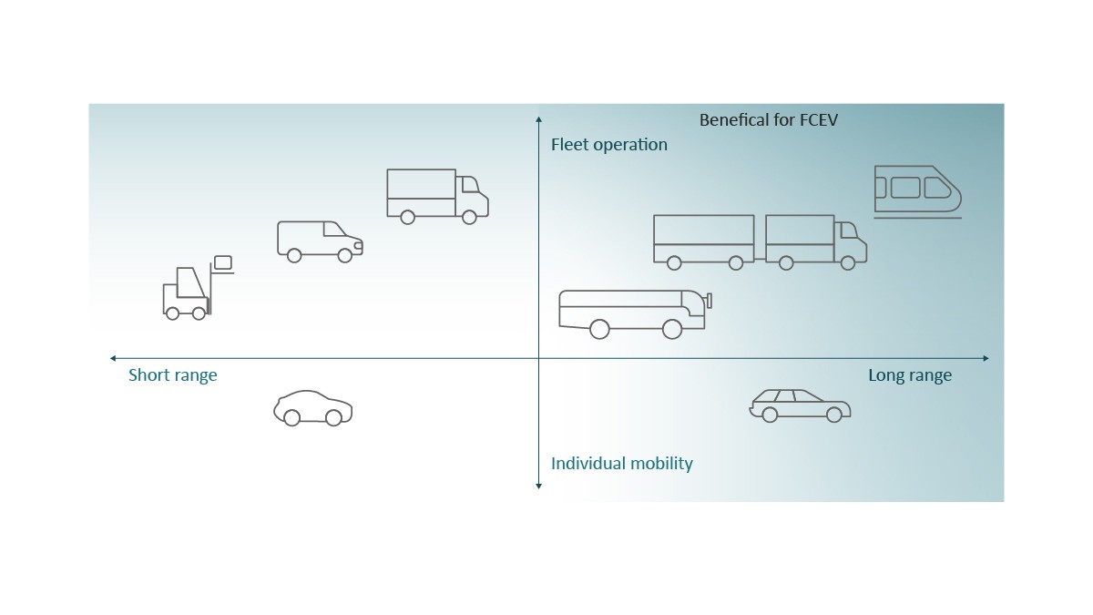
For that reason, the fuel cell should not be viewed as competing with battery-electric powertrains in transportation, but rather as a useful addition that can accelerate the conversion to a sustainable, climate-neutral energy supply in the transportation sector. Fuel cell powertrains will initially make their way into commercial vehicles for intercity transportation (trucks, long-distance buses); see Figure 2. However, larger cars and vans that regularly travel relatively long distances will also make use of the advantages of hydrogen operation as long as the corresponding infrastructure for generation and distribution has been put in place.
On the way to mass production
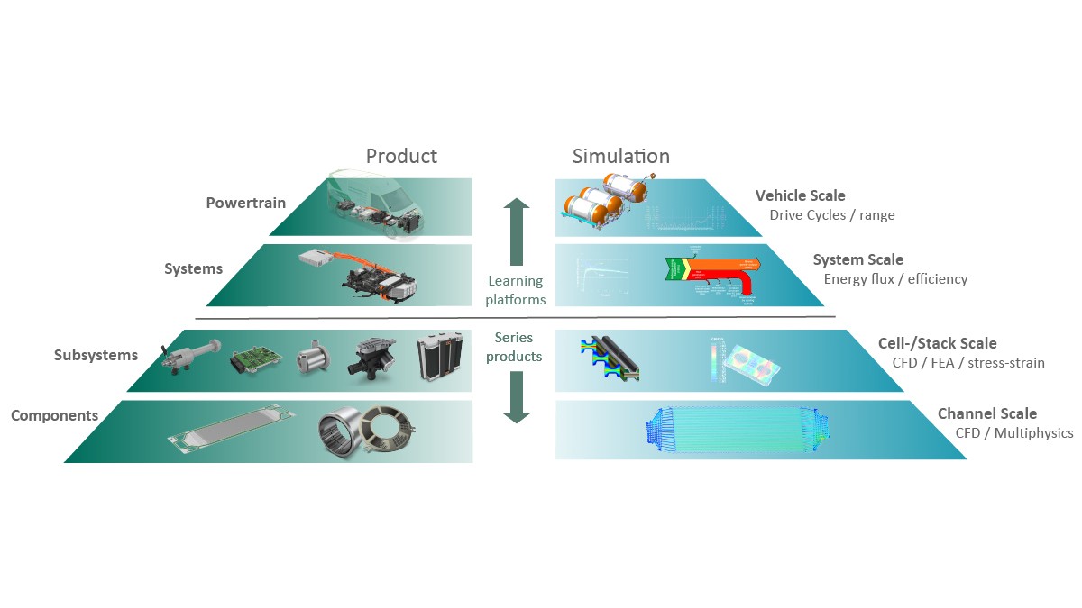
The high manufacturing costs resulting from the fact that fuel cells still cannot be produced in high volumes represent an obstacle to the use of fuel cells in road vehicles. The key to more economical manufacturing lies in the efficient scale-up to mass production of the most important components and subsystems. This scale-up is at the core of the Schaeffler strategy, as shown in Figure 3. Schaeffler sees the system and powertrain levels as development platforms enabling the system and integration know-how required for close cooperation with customers to be acquired. Parallel development of product and simulation methods takes place on all levels.
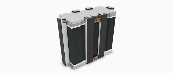
A fuel cell stack consists of membrane electrode assemblies, bipolar plate modules, end plates, media adapters, and the clamping system. Three media lines are needed to operate the stack: the hydrogen circuit, the air path, and the cooling circuit. Each of the three media systems contains a series of subcomponents, which together with the electronic and electrical components are known as the BoP (Balance of Plant). Component development is being carried out for all BoP modules and is presented in the following.
Components for efficient stacks
The bipolar plate is a key component in a PEM fuel cell. It accounts for up to 80% of the stack weight and up to 65% of the stack volume and is therefore extremely important for the power density. The same applies to the function: The bipolar plate separates and distributes the process gases and removes the product water. Conduction of the generated current between cells and homogeneous distribution of the coolant are other key tasks of this component.
Bipolar plates can generally be made of graphite or metal. Schaeffler sees three key advantages of metal plates:
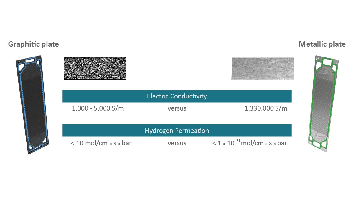
For one thing, the overall stack volume is mainly determined by the wall thicknesses. With graphite bipolar plates, a remaining wall thickness between channel structures of 700–800 m can be achieved; this results in a distance between cells of more than 3 mm. With metal plates, the thickness can be reduced to 50–100 m and results in a cell spacing of less than 1 mm. At least as important for the energy density is the second advantage that metal bipolar plates offer: They combine a significantly higher electrical conductivity with a much lower permeability to hydrogen, as shown in Figure 4.
Thirdly, the higher brittleness of graphite directly affects the productivity of the manufacturing process. It makes fully automated handling more difficult because great care must be taken and thus practical limitations are imposed on the handling. To reach a manufacturing time of less than one minute per part (including coating), a larger production area is needed.
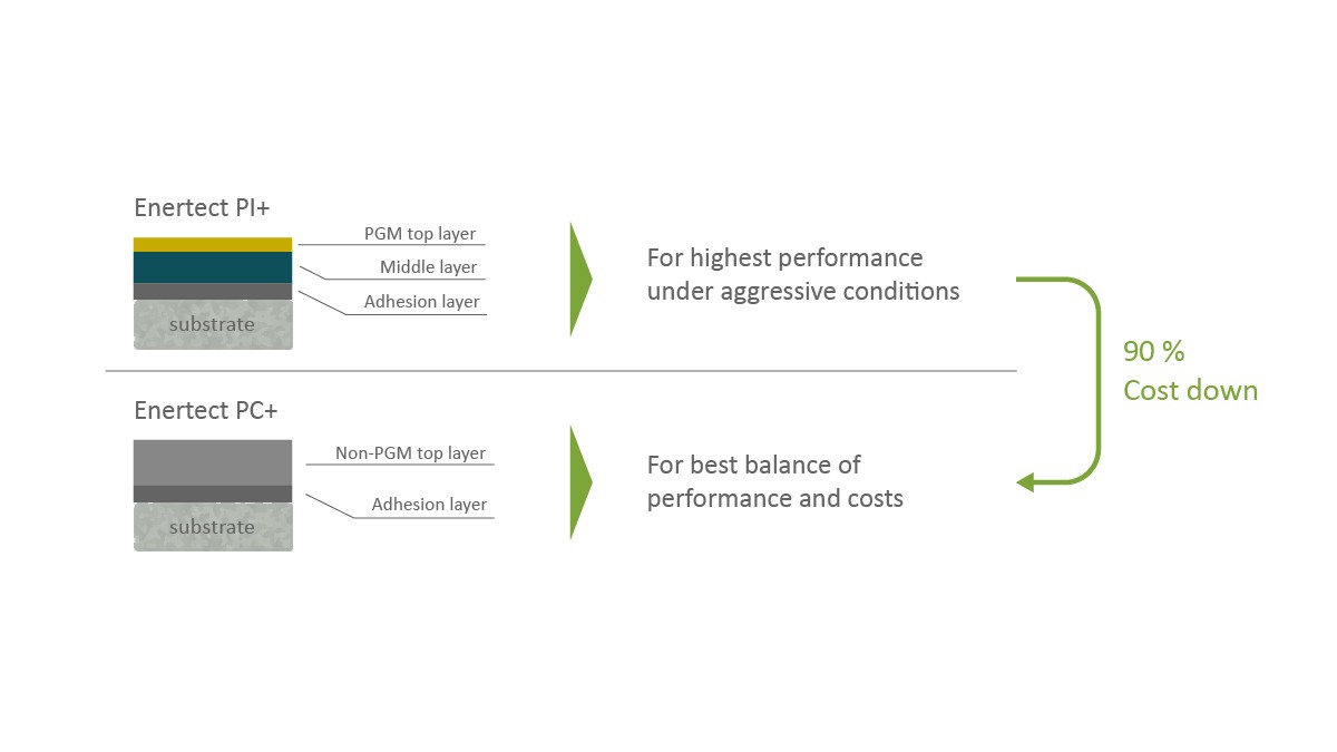
A unique technical feature of Schaeffler’s metal bipolar plate modules is the coating system. The reason for coating the stainless steel plates at all, even though they are not subject to corrosion, is down to the phenomenon of passivation. Over the course of the service life, the chromium contained in the alloy reacts with oxygen to form a layer of chromium oxide on the plate surface, thereby impairing the conduction of electrons at the transition from the membrane electrode assembly (MEA) to the bipolar plate. The task of the coating is to maintain the high electrical conductivity over the entire service life and prevent metal ion contamination of the MEA. The ions would accumulate over time both on the active catalyst material and at the sites in the membrane through which protons can pass. For this reason, Schaeffler is currently developing several coating systems especially for bipolar plate modules with the “Enertect” family. One is based on platinum group metals (PGMs) for very high service life requirements, and another is based on a low-cost carbon coating; see Figure 5. With its competence in surface technology, Schaeffler can continue offering customers application-specific coating development and balance costs with performance as required. The coating systems are applied using the physical vapor deposition process (PVD), which has already proved suitable for large-scale production – such as in the production of heavily loaded valve train components.
Current supply chains for bipolar plate modules are complex; i.e., fuel cell manufacturers depend on various internal and external suppliers, each of whom only assumes partial steps in the overall manufacturing process. A bipolar plate that can be manufactured scalably and reproducibly with a high quality arises when the process steps are linked in the company’s production facilities.
The processes of shaping and coating of very thin steel parts are related to manufacturing processes that Schaeffler has traditionally used for engine and transmission parts, although thicknesses of 50–100 m present additional challenges. Chemically bonded joining of the two flow field plates that a bipolar plate module is made up of is a well-known process on Schaeffler production lines. A laser welding process is used and refined for this product. The application of the seal plays an important role, and not just for quality reasons. This process step also plays a key role in the throughput rate, or cycle time, in a highly automated production environment. Quality assurance is also important, especially in light of the fact that a single 120 kW fuel cell stack comprises more than 300 bipolar plate modules.
In order to demonstrate the ability of Schaeffler’s solution to be scaled up to high-volume manufacturing, the company installed a pilot plant at the company headquarters in Herzogenaurach in 2022. It has an annual production capacity of more than 700,000 bipolar plate modules for mobile fuel cell applications. The plant is also designed to enable production of larger bipolar plates for electrolyzers (up to 1800 x 600 mm). The individual process steps in the pilot plant designed by Schaeffler’s the in-house Special Machinery department are already completely or at least highly automated. A roll-to-roll process in which all process steps are first carried out on an endless metal foil and the plates are only separated after application of the seal has also already been designed. The pilot plant is embedded in a new hydrogen center of excellence established at the Herzogenaurach location for the continuous further development of the Schaeffler portfolio. The center has a large testbed for electrolyzer technologies for fuel cells at the component, stack, and overall system levels.
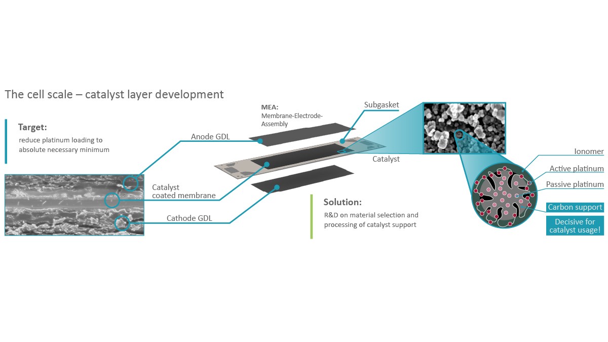
The second key component for economical stack manufacturing is the membrane electrode assembly (MEA), which makes up half of the total costs of a fuel cell stack. The main cost driver here is the amount of platinum needed as a catalyst for oxidation. The platinum amount is mainly influenced by how well the applied material can be kept active over the lifetime of the fuel cell. Schaeffler is therefore conducting intensive research on designing the structure of the catalyst support and its manufacturing in such a way that the active use of the platinum is maximized; see Figure 6. The structure of and the manufacturing process used for the catalyst support are important factors in ensuring this; materials research is focused on the technical function and on a process technology enabling economical large-scale production.
Subsystems for efficient operation
The efficiency of a fuel cell system is mainly determined by the stack and the subsystems for media conveyance. Additionally, an efficient electrical system and its control determine the efficiency with which the chemically stored energy in the hydrogen can be utilized.
Air supply
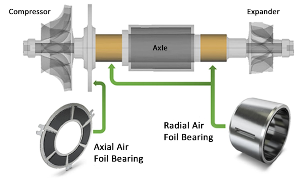
Air is usually supplied to mobile fuel cell systems using high-speed electrically driven turbocompressors. In vehicles with internal combustion engines, such compressors have only been used for short-time acceleration processes. They are thus usually designed for about one million load cycles. The requirements in the air path of a vehicle fuel cell are far higher. A service life of several thousands of hours at maximum speeds of up to 200,000 rpm is required. One particular challenge in this context is to avoid bearing damage because oil or grease lubrication is ruled out due to the required purity of the process air. Schaeffler has applied its bearing know-how toward the development of various axial and radial air foil bearings [5]. With this design type, bent bump foils are attached between the bearing ring and the shaft – that is, the rotor of the compressor drive – on the ring side as shown in Figure 7. Because the foil lifts off the shaft at relatively high speeds, friction-free and lubrication-free operation can be achieved. Due to the principle, however, this design prevents mechanical contact between the rotor and the stator in all operating states, i.e., even when the rotor is at a standstill.
Schaeffler’s bearing know-how combined with its electrical knowledge yields a compact and mechanically high-quality drive unit comprising an electric motor and power electronics. With external partner TTI contributing the compressor wheel know-how, Schaeffler can design and manufacture the compressor as a complete unit, as shown in Figure 8. Currently there are two power stages with 60 kW and 120 kW, respectively, foreseen for this. The first prototypes are planned for mid-2023.
Passive hydrogen recirculation
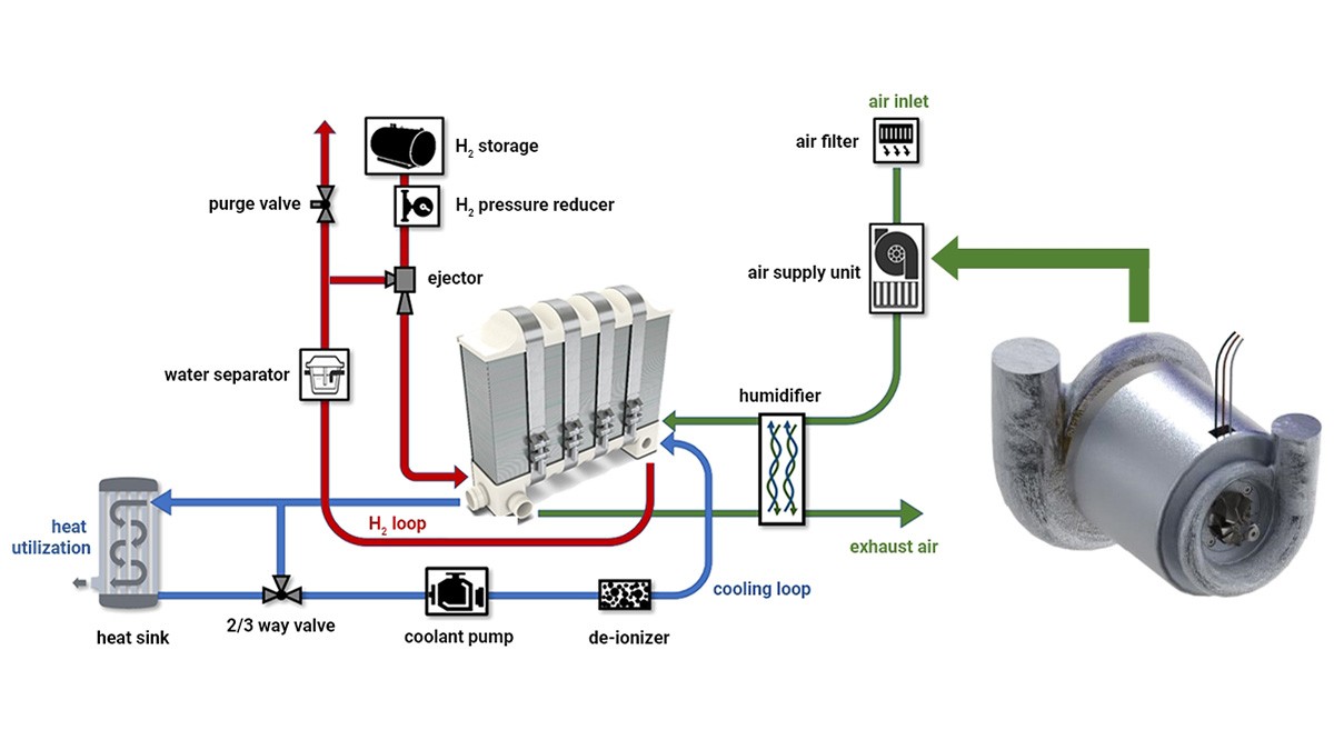
In the hydrogen path, the recirculation of unused hydrogen is the key lever for improving the efficiency. Theoretically, a continuously working pump would be sufficient for the mass transport, but such a solution is associated with a relatively high power consumption. Passive recirculation via controlled nozzles based on the Venturi effect is significantly more energy-efficient and space-saving. For this, various design solutions are available for transporting the residual hydrogen amounts, which depend on the respective operating points. Research has been done in the past on multistage and on adjustable nozzles, among other things. Intensive CFD simulations with multiple designs at Schaeffler show that an adjustable two-stage nozzle as shown in Figure 9 provides the best cost-to-benefit ratio. A decisive quality criterion for these nozzles – similarly to high-pressure fuel injection in an internal combustion engine – is the long-term reproducibility of precise volume control. The test bench tests conducted by Schaeffler in cooperation with an initial customer show that the Schaeffler nozzles offer this reproducibility.
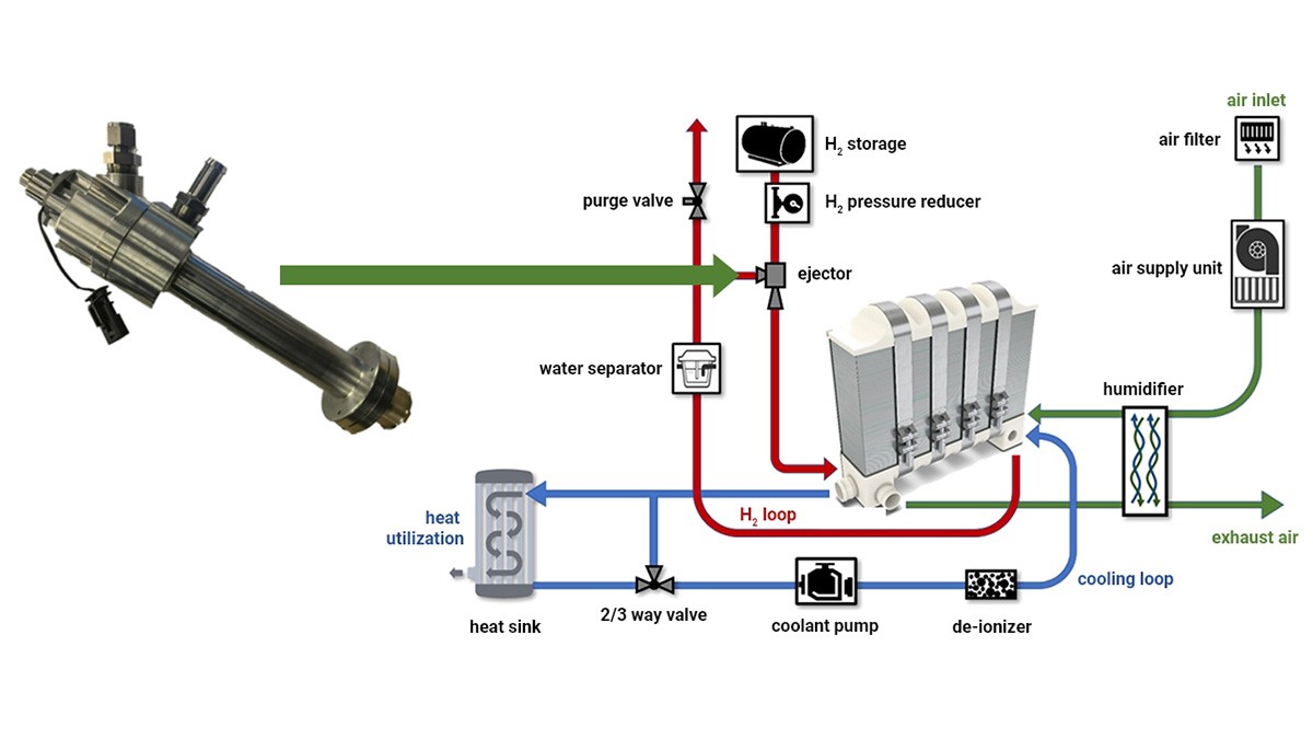
Coolant management
The efficiency of electrochemical processes always depends on the temperature staying within certain windows. Although these are significantly larger in the fuel cell than in lithium-ion batteries due to the lower energy conversion efficiency of the fuel cell, significantly larger amounts of heat have to be dissipated, which is why coolant management is of great importance in a fuel cell powertrain. The construction of different, possibly interacting, cooling circuits can be significantly simplified through the use of standardized controllable valves, as shown in Figure 10.
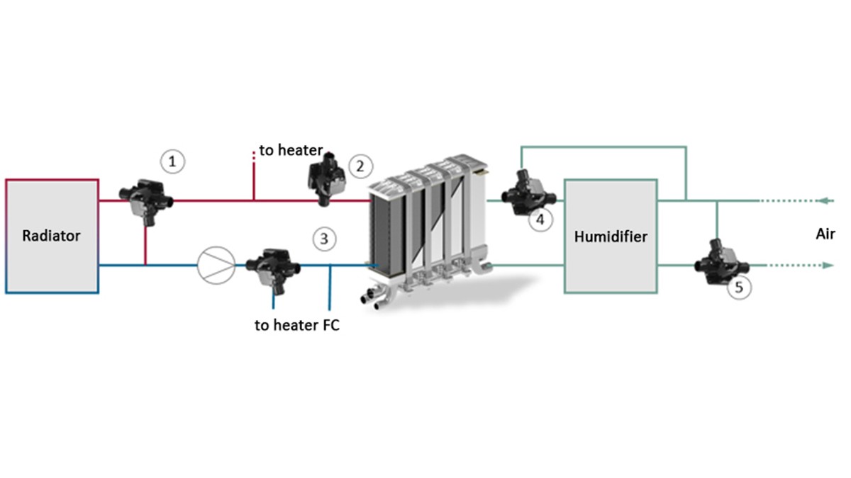
For this application, Schaeffler offers the thermal management modules (TMMs) that have been proven a million times over in conventional powertrain technology or Single Smart Valves (SSVs) for fuel cell systems. The same components built almost identically can also be used in the air path, for example, to bypass the humidifier or intercooler.
Control
Ultimately, the efficiency of the fuel cell is influenced at least as much by the system control as by the design of the individual subsystems. Power and scalable control unit hardware forms the basis for this. With the PROtroniC, Schaeffler can supply a hardware solution that has been proven to be suitable for prototypes and low production volumes. In addition, Schaeffler Engineering has developed software modules for firmware that include fuel cell-specific functions such as monitoring for leaking hydrogen. A mass production-ready solution can be derived on a customer-specific basis at a correspondingly low cost.
Complete system as a development platform
Rapid scale-up of fuel cell production requires that components and subsystems be made ready for mass production as quickly as possible. It therefore makes sense to design them consistently for interaction within an overall system right from the start. That is why Schaeffler decided to develop its own complete fuel cell system for mobile applications as a learning platform. A key objective of the tests with the complete system is the optimization of the simulation tools. The reliable prediction of wear and aging behavior in field use is an especially important field of research.
The system limits have been further expanded in a demo vehicle built by Schaeffler based on the Volkswagen e-Crafter delivery van, as shown in Figure 11. A relevant question in the design of fuel cell powertrains concerns the specification of the sizes and powers of the subsystems. In general, it can be said that a large electrical storage device assumes a greater share of the power supply for acceleration processes and that the fuel cell can correspondingly save on dynamics. A 13 kWh battery known from other Volkswagen models is used in the demo vehicle, allowing a maximum power output of 85 kW. The fuel cell system used is designed for a continuous output of 50 kW. The axle drive is provided via an electric axle, also originating from Schaeffler, with a maximum output of 140 kW and including the associated power electronics.
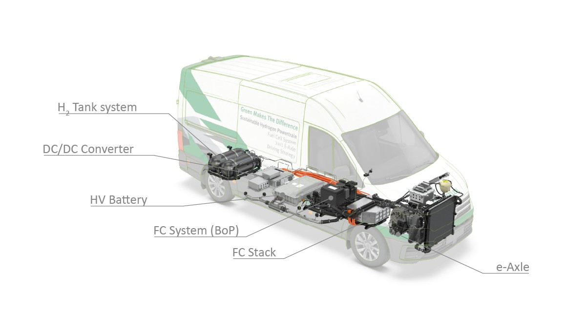
Overall, this configuration with a relatively low dynamically operated fuel cell is advantageous for the commercial vehicle sector, with the spread between the nominal and continuous power requirements increasing with increasing vehicle weight. Schaeffler will further optimize the presented concept in the future. The goal is to move the electric axle drive to the rear axle of the vehicle in order to provide space for the fuel cell system in the front end. This shift will also create room for further hydrogen tanks in the underbody. In the future, the performance of the fuel cell may also be increased and the battery size further reduced so that higher dynamic requirements can also be met with the help of the fuel cell.
Summary
Due to the high energy density and short refueling time, as well as the future energy system infrastructure, hydrogen fuel cells can favorably complement battery-electric powertrains. With the scale-up to mass production of components and subsystems, Schaeffler is contributing decisively to driving down manufacturing costs for future fuel cell systems.
At the component level, Schaeffler is developing a bipolar plate module that is designed throughout for scale-up to high-volume manufacturing. One outstanding technical feature of the metallic bipolar plate is a coating system developed by Schaeffler that prevents passivation and metal ion contamination of the MEA, thus providing for a long life. On the level of the subsystems, the media supply plays an important role in determining the performance and durability of the fuel cell. For the air path, Schaeffler is developing a compressor with an air foil bearing that enables friction- and lubrication-free operation. For the hydrogen path, development of recirculation ejectors with precise and reproducible volume control is underway. Schaeffler is also working on subsystems for thermal management and electronic control of the fuel cell system as well as on prototype stacks as complete modules. The development platform used for this is a fuel cell system with a Schaeffler stack that will be used for the first time in early 2022 in a demo vehicle based on a Volkswagen Crafter.
Schaeffler covers all technical facets from the start of production for mass production-ready bipolar plate modules to system testing in real vehicles to enable rapid ramp-up to high-volume manufacturing of fuel cells. Once this scale-up has succeeded, there will be another mass production-ready alternative for climate-neutral mobility.
[1] International Energy Agency (Hrsg.): Renewables 2021: Analyses and forecast to 2026. Revised version. Paris, 2021. https://iea.blob.core.windows.net/assets/5ae32253-7409-4f9a-a91d-1493ffb9777a/Renewables2021-Analysisandforecastto2026.pdf
[2] Handwerker, M. et al.: Comparison of Hydrogen Powertrains with the Battery Powered Electric Vehicle and Investigation of Small-Scale Local Hydrogen Production Using Renewable Energy. In: Hydrogen (2021) Nr. 2, S. 76-100, doi: 10.3390/hydrogen2010005
[3] International Energy Agency (Hrsg.): Global EV Outlook 2021. https://www.iea.org/reports/global-ev-outlook-2021/prospects-for-electric-vehicle-deployment
[4] Frost & Sullivan (Hrsg.): Global Green Hydrogen Production Set to Reach 5.7 Million Tons by 2030, Powered by Decarbonization. https://www.frost.com/news/global-green-hydrogen-production-set-to-reach-5-7-million-tons-by-2030-powered-by-decarbonization/
[5] Schutzrecht EP 3099951B1: Aerodynamisches Luftlager und Verfahren zu dessen Herstellung. 2019
[6] Rosenfeld, D. C. et al.: Comparison of advanced fuels. Which technology can win from the life cycle perspective? In: Journal of Cleaner Production 238 (2019), doi: 10.1016/j.jclepro.2019.117879
[7] Sternberg, A. et al.: Greenhouse Gas Emissions for Battery Electric and Fuel Cell Electric Vehicles with Ranges over 300 Kilometers. Freiburg: Fraunhofer ISE, 2019. https://www.ise.fraunhofer.de/content/dam/ise/en/documents/News/190815_LCA-BEV-FCEV_Results_EnglishVersion.pdf
[8] FVV (Hrsg.): Zukünftige Kraftstoffe: FVV-Kraftstoffstudie IV. Frankfurt am Main, 2021. https://www.fvv-net.de/fileadmin/user_upload/medien/download/FVV__Future_Fuels__StudyIV_The_Transformation_of_Mobility__H1269_2021-10__EN.pdf