Bits Meet Metal ─ Optimal Electric Drive Trains by Integrating Innovative System and Software Functions
Götz Rathke | Björn Stehle
Schaeffler leverages the potential of an overarching development approach to realize the optimal electric drive train by holistically analyzing and improving components as well as software functions. This involves designing the systems with overall performance in mind such that all objectives are fulfilled to their maximum extent while ensuring that the requirements of the components are taken into account accordingly and that their technical capabilities are exploited. Examples of system-related developments at Schaeffler include the functional integration of hardware and software control of e-axles and a function for adjusting the inverter switching frequency that predictively and optimally counteracts temperature problems and, thus, performance limitations in electric drive trains under full-load operation. The outcome of this approach, bundling the system and software expertise of Schaeffler, is added value by smart systems with high functional quality that promote the transformation to environmentally friendly electric mobility.
Increasing development requirements
The automotive future can already be experienced today as a wide variety of electric vehicles in different segments have been available in the marketplace for quite some time. In Germany alone, more than 350,000 dedicated battery-electric vehicles were newly registered in 2021. This corresponds to 13.6 percent of total new registrations and represents an increase of 83.3 percent compared to the previous year [1]. One reason for the more pronounced market penetration of electric vehicles is the high level of innovation they embody as well as the advanced technologies integrated in their drive trains. This, in turn, enables them to better meet the expectations of potential customers, including:
- Good range that is not worse than that of vehicles with combustion engines
- Minimal operating noise
- Reasonable price/performance
- Good drivability and driving pleasure
- Attractive design
- Fast battery charging cycles
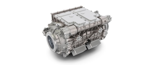
As such, the reluctance to buy that has prevailed up to now is gradually being overcome. In drive train development, these demanding targets lead to a myriad of technical requirements with regard to e.g. modularity, NVH performance, driving dynamics, cost, package, power density, efficiency and durability (Figure 1).
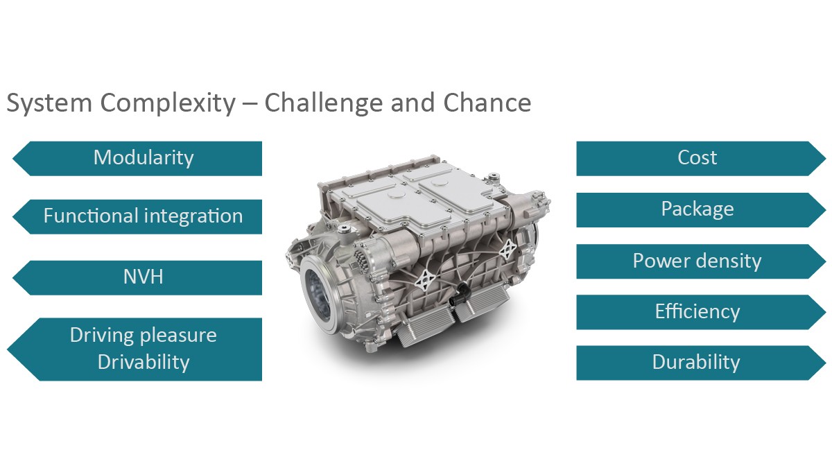
The conflicting objectives arising from the somewhat opposing development requirements cannot be resolved by a drive train design philosophy that is limited to the component and subsystem level, but by sophisticated and perfectly balanced systems. Schaeffler therefore relies on a holistic system development approach for the electric mobility domain. On the one hand the systems are designed focusing on overall performance such that they meet all design requirements in the best possible manner while on the other hand attention is also paid to ensuring that the requirements of the components are taken into account accordingly and that their technical capabilities are fully exploited. Consistent system orientation along the entire development cycle likewise produces substantial added value beyond the sum of the individual components’ characteristics . Here, a practical example from Schaeffler is the development of an e-axle, whereby the operative weight was reduced from an initial 250 kg to just 120 kg through clever system integration and optimization.
System development resolves conflicting objectives
Schaeffler's approach to system development of electric drive trains is illustrated below using two examples. In this context, Schaeffler implements new functions for individual modules in hardware and software that improve the performance of the overall system:
- Integrated power electronics: Merging power electronics of the electric motor and the transmission control system.
- Proactive inverter switching frequency adaptation (ProISA): Avoiding power derating as overload protection in the electric drive train by cleverly varying the switching frequency, thus balancing the losses between the motor and power electronics.
These new functions make a substantial contribution to resolving key trade-offs in developing electric drive trains:
- Installation space versus functional scope: As available installation space is becoming scarcer due to the increasing number of components and systems in vehicles, new, advanced vehicle functions require ever more powerful control units with higher computing power.
- Driving pleasure and continuous full-load driving versus efficiency and power reserves: Electric drive trains offer full torque from the first revolution and in so doing can provide a great deal of driving pleasure. If the driver makes frequent use of the available power, however, individual subsystems of the electric drive train may reach their temperature limits under certain circumstances. As a result, to protect various components, the system power is then throttled back, leaving the driver with less than maximum output.
Integrated power electronics
In highly integrated electric drive trains such as e-axles, the electric motor forms a modular unit with the transmission [2]. By contrast, the management system for the transmission actuator and electric motor employed in today's concepts is still widely realized using two separate control units. The power electronics of a high-voltage drive system are normally subdivided into a low-voltage and a high-voltage section. The low-voltage section controls the motor function via the control board (control path) and establishes the electrical connection to the vehicle's low-voltage network. The control path operates in the low-voltage range with a 12, 24 or 48 V on-board electrical system, whereas the high-voltage drive train voltage (800 V) is applied to the power path. The control board gives the power electronics their intelligence. It does this by regulating the torque output or speed of the high-voltage traction motor by adjusting the frequency, phase angle and voltage of the rotating field generated. Separate from the power electronics, the transmission control unit coordinates the actuators. Communication between the control board for the power electronics and the transmission control unit occurs indirectly via the vehicle's communication bus.
A new control unit architecture from Schaeffler now reorganizes the software and hardware components of the power electronics and actuator controller (Figure 2). Instead of the previous demarcation between the engine and transmission control system, focus is placed on the function-oriented merging of the actuator controller and the control board for the power electronics.
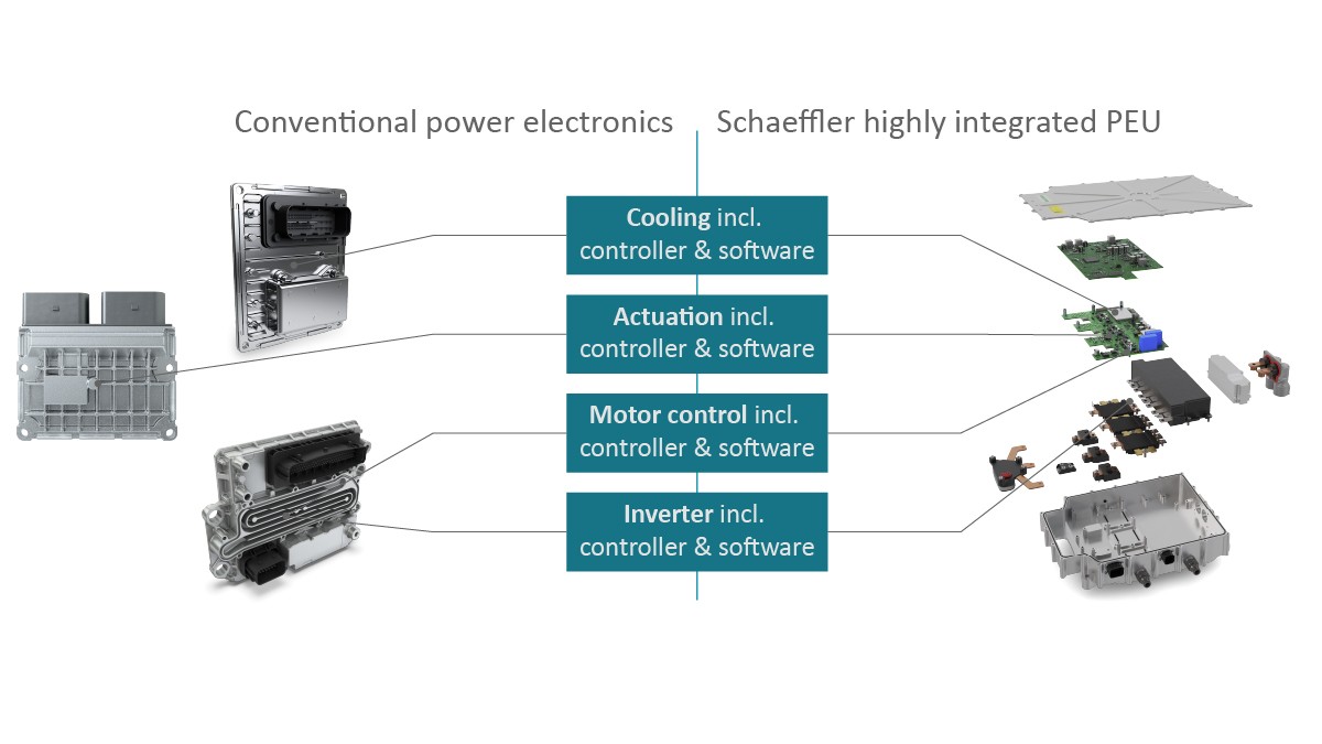
On the hardware side, centralizing the control functions on one board realizes savings at the component level as many electronic components, such as the microcontroller, can be used for both control circuits. It also takes fewer resources to manufacture the control module, less installation space is required and mounting on the transmission is simpler. The concept likewise requires fewer cables and connectors e.g. to connect to the on-board electronic’s bus system. With respect to sustainability, shared use of the microcontroller also leads to a noticeable reduction in the need for materials. And from a functional perspective, the control accuracy of the overall system increases. By combining the motor and transmission control system, the overall functionality of the drive train can be better coordinated. This, in turn, improves efficiency and passenger comfort. The latency between the motor and transmission control parts is reduced, for example. The functional quality of a decoupling unit benefits from direct communication between speed synchronization via the electric motor and the active control of the shift element. The shift times for two-speed transmissions are also minimized because the speed of the electric motor can be better synced with a gear change. The bus load can also be significantly reduced since data is now exchanged via internal control unit variables. Yet another benefit is that the variables are now available in the correct time context and can be processed accordingly as opposed to the asynchronous data provided by the CAN bus, for example.
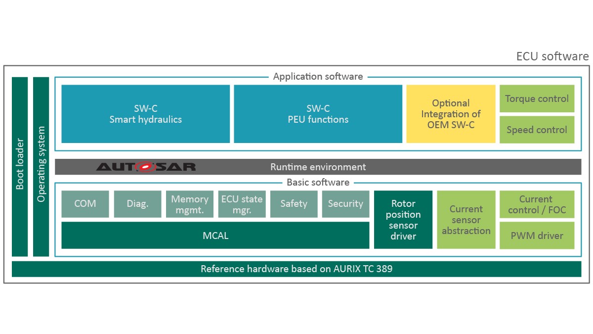
Schaeffler has created a modular architecture for the control software that can be adapted as required to harmonize with the different requirements of various development projects. Customers of the hardware can tailor the required software package and support provided by Schaeffler for creating dedicated computational code blocks for the system application (Figure 3). In the process, the Schaeffler content can encompass:
- Just the AUTOSAR basic software adapted to the electronics
- The complete software functional scope for an e-axle, including integration and application (as a turnkey project)
- Integration of OEM-specific program modules at Schaeffler
- The supply of software modules for integration at the OEM for its control unit platform
ProISA: Avoiding derating for overload protection in the electric drive train.
Considering limit curves is not only important when it comes to comfort, but also plays a key role in complying to maximum temperature limits in the drive train. Temperature development of the electric powertrain components largely depends on the load at which they are operated. For example, if an electric vehicle is operated at full load for an extended period, the temperatures in the electric motor and inverter will rise accordingly. To reliably prevent the components from overheating, the power electronics actively limit the current and, thus, the power output of the drivetrain. The way in which this protective function is applied corresponds to the state of the art. This "derating", as it is called, represents a significant automatic intervention that is noticeable to the driver in the form of reduced power.
Schaeffler developed proactive inverter switching frequency adaptation (ProISA) to shift the derating limit for high-load requirements to allow the powertrain to operate at full power for as long as possible. This function is based on Schaeffler's comprehensive overall system knowledge in the field of electric drive trains. Instead of regarding the motor and inverter as a thermal unit according to today’s common practice, Schaeffler analyzed the individual characteristics of both components and leveraged them for the overall system. After all, the electric motor and inverter respond differently from a thermal perspective. In many high-load scenarios, frequently only one component initially reaches its temperature limit, while the other is still unproblematic (Figure 4).
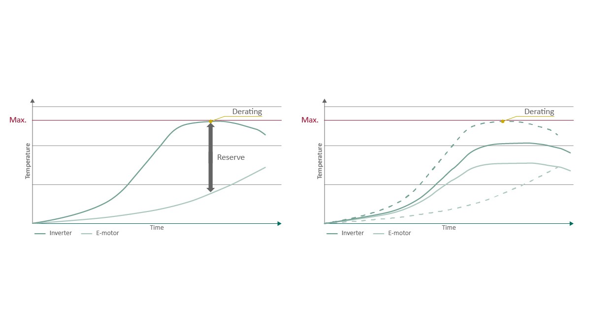
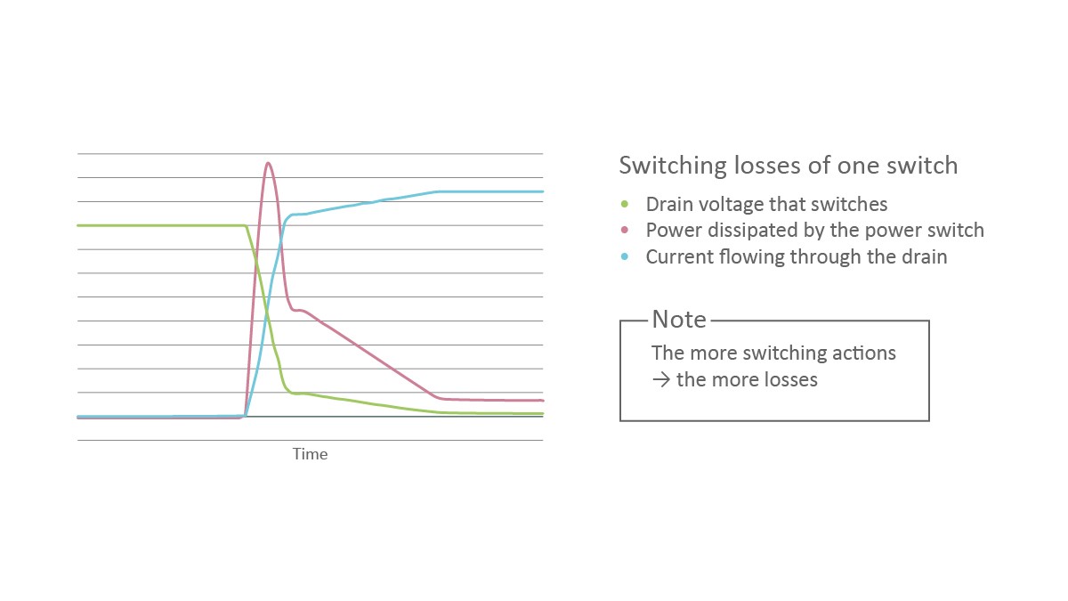
ProISA from Schaeffler utilizes this phenomenon for thermal balancing of the components by varying the inverter switching frequency. The heart of the approach is the fundamentally opposing behavioral response of the two components. With the inverter, losses and, thus, temperatures increase in parallel with the switching frequency. This results from the fact that electrical power is being dissipated across the on-state resistance and therefore heat is generated primarily during the actual switching process of the MOSFET in its transition phase (Figure 5). The more switching operations the inverter performs within a specific time interval, the more thermal energy is introduced into the power switches. With the electric motor, the iron and copper losses and, thus, temperature levels decrease as the switching frequency increases for better approximation to an ideal rotating field.
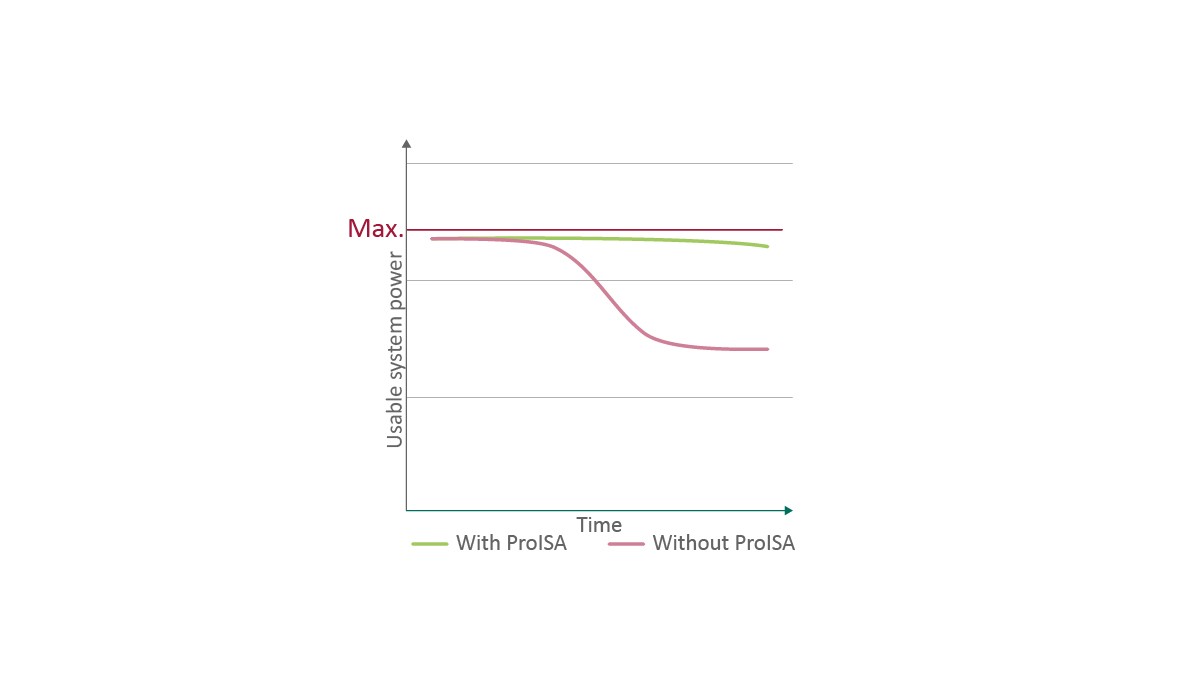
By making momentary adjustments to the switching frequency, ProISA from Schaeffler reduces the temperature of the component currently subjected to the highest load. The resulting higher heat generation in the other component can then be tolerated as long as the limit temperature is not exceeded here either. ProISA thereby forms a pre-stage of the derating protective function. It does not replace the function but is instead designed to minimize its intervention frequency or even make it unnecessary by fully utilizing the thermal reserves of all system components (Figure 6). Derating only occurs when the system as a whole reaches its temperature limit.
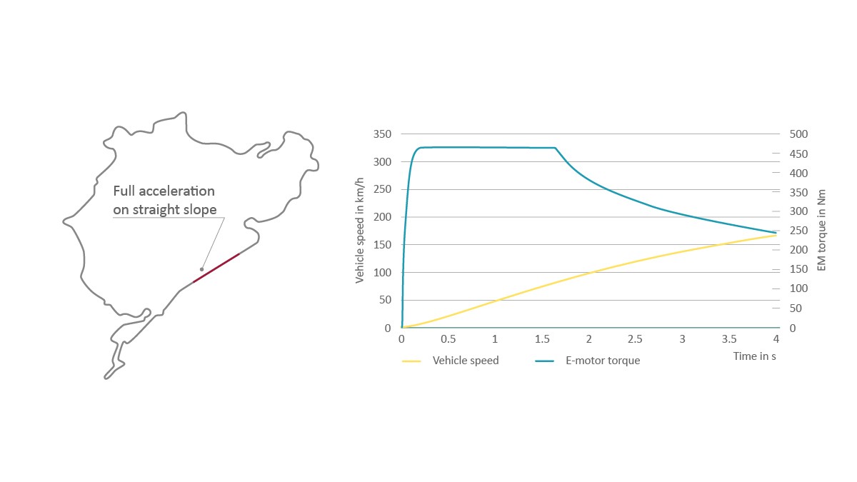
The following illustrates the way ProISA works using two examples during a simulated lap on the Nürburgring Nordschleife. The advantage of this racing circuit is that different high-load situations occur in short intervals that are also experienced in real-world conditions, albeit over more space and time.
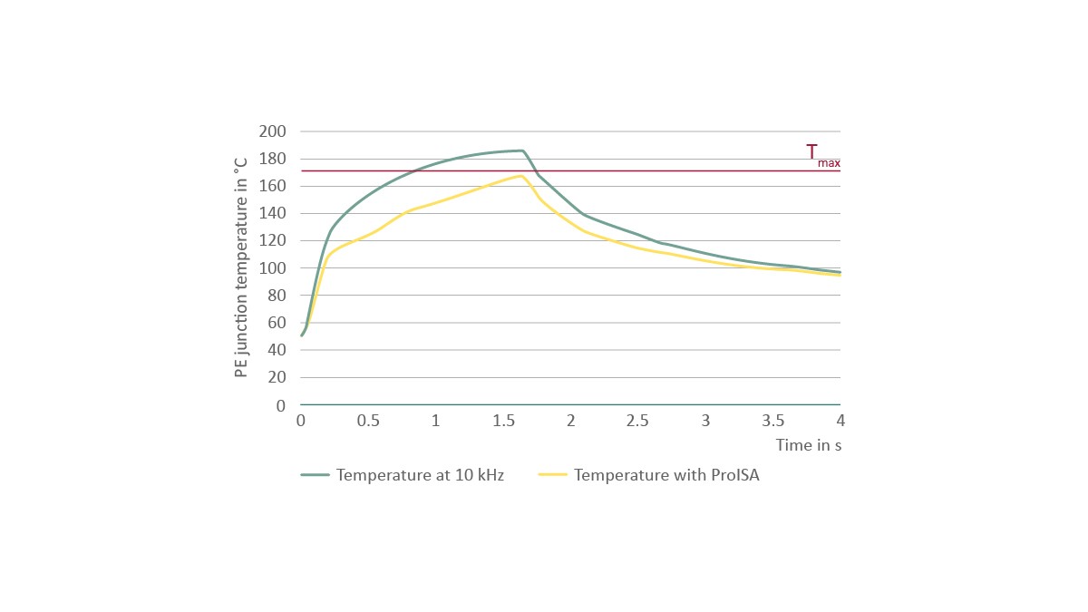
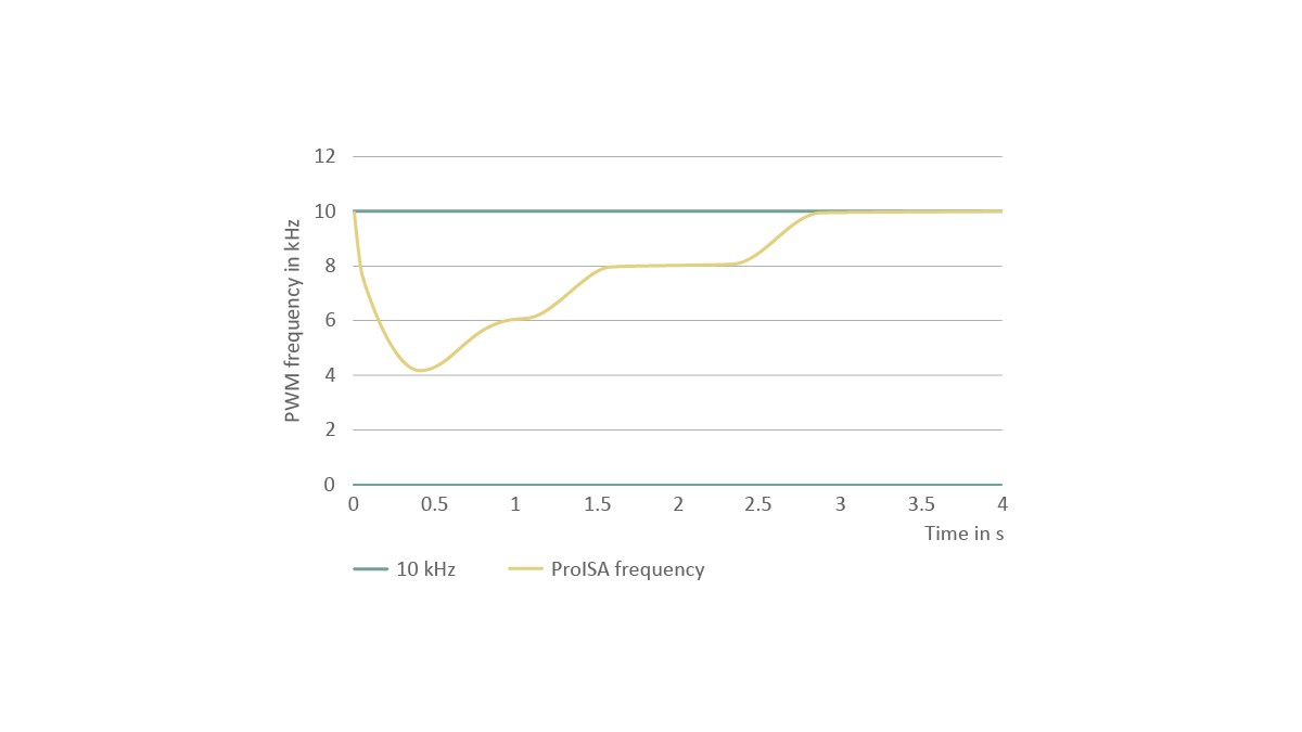
In the first example, driving with an increased torque requirement (Figure 7) (right) reveals a characteristic speed and torque curve over time. This situation is particularly challenging for the inverter, which is why we will focus on it in the following discussion. Figure 8 plots the temperature of the inverter. The red line shows the limit temperature of 170 °C, which must not be exceeded to protect the inverter’s electronic components. The temperature curve of an inverter with a switching frequency fixed at 10 kHz is shown on the right. The maximum temperature is exceeded after only about 0.8 s such that active derating must be applied, whereas temperature levels always remain below the permitted value (light blue curve) with the continuous frequency adjustment by ProISA. Figure 9 plots the frequency variation of the inverter configured for this situation. The upper limit of the control range is the regular inverter frequency of 10 kHz; the lower limit is determined by the system characteristics (here, NVH response in particular). In this example, it is 4 kHz.
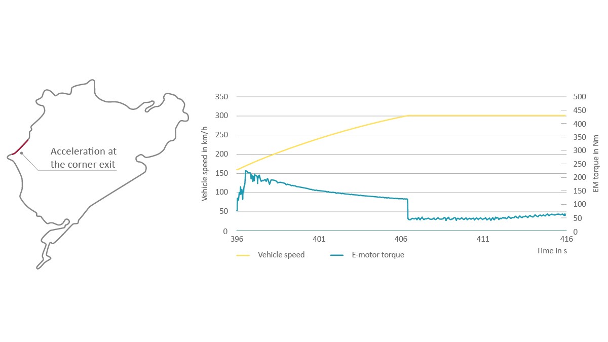
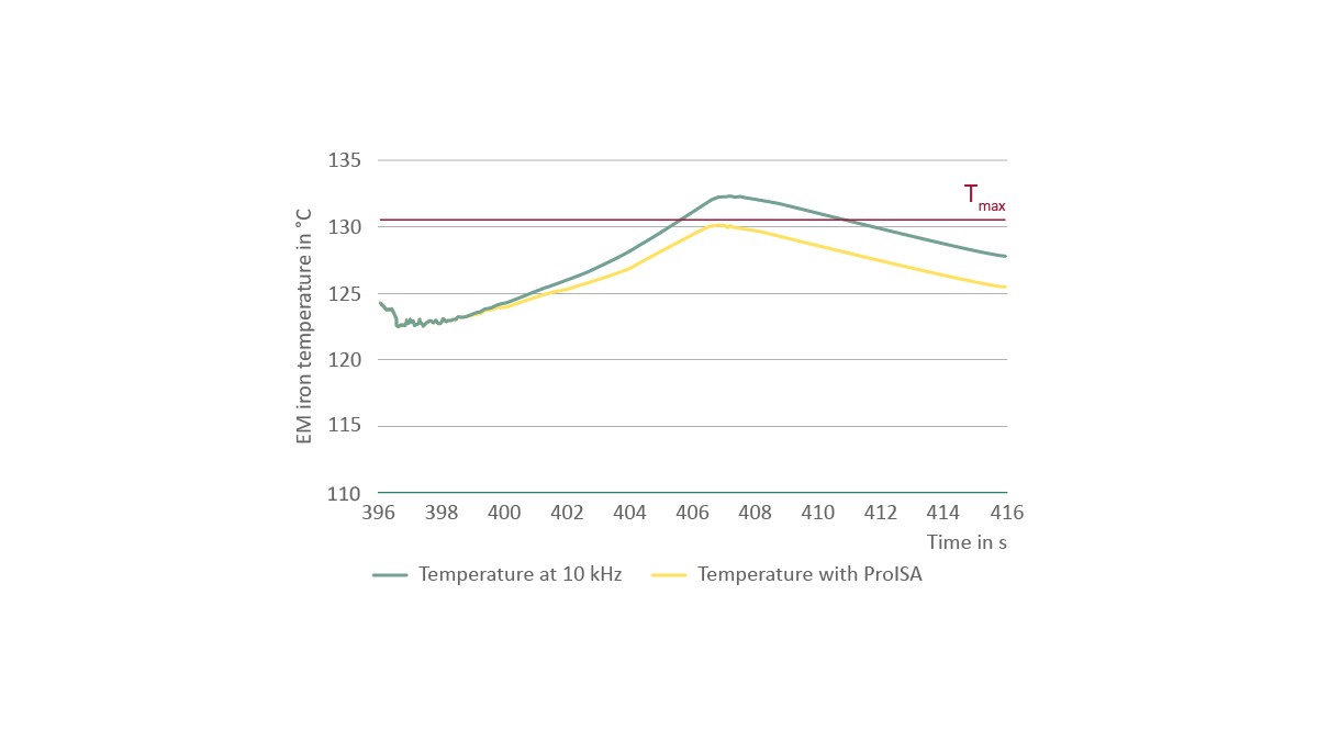
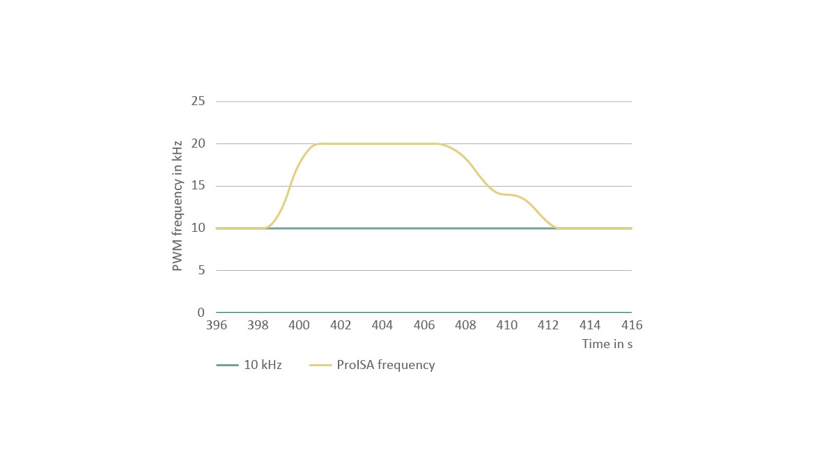
The second example of the ProISA application ─ an extended full-load run during which braking is required, followed by acceleration ─ is especially thermally demanding for the motor. Figure 10 (right) shows the progression of vehicle speed and torque over time in this driving situation. The temperatures that occur are shown in Figure 11. In contrast to the previous example this time the motor temporarily exceeds the temperature limit without ProISA, while permitted temperatures remain within the motor’s limits with ProISA. Here, the function increases the switching frequency from 10 to 20 kHz to reduce motor loss and, thus, heat generation (Figure 12).
Unlike the previous example, however, this involves switching to the high frequency at a very early stage (even before braking and acceleration). The reason for this has to do with the high thermal mass of the motor. The resulting delay in cooling must be taken into consideration by the thermal management strategy. Schaeffler has implemented a proactive adaptation function in ProISA for this purpose. The function causes the inverter to switch to the higher frequency even before a temperature-critical situation occurs for the motor to avoid its possible subsequent overheating early on as well as to prevent derating of the drive train in demanding situations such as acceleration after braking.
Across the entire simulated lap on Nürburgring Nordschleife circuit, ProISA actively prevented 25 derating interventions by the electric motor controller, which otherwise would have reduced total power output over a time window of 52 seconds. With ProISA, the lap time could be improved by 5 seconds.
Summary
In the development of electric vehicles, the diverse and sometimes conflicting requirements encountered can no longer be implemented based on the operative function of individual components, but instead only in their interaction with respect to the overall system. To this end, Schaeffler leverages the potential of an overarching development approach to promote system integration in electric drive trains and generate new functions from within the system. This involves designing the systems with overall performance in mind such that all targets are fulfilled as far as possible while respecting the requirements of the components and fully exploiting their technical capabilities.
An example of innovative system functions for e-axles are the integrated power electronics, which combine the hardware of the power electronics for the electric motor with that for the transmission control system. Schaeffler has created a modular architecture for the integrated power electronics control software that can be adapted as required to harmonize with the different requirements of various development projects. The ProISA (proactive inverter switching frequency adaptation) function comes into play for thermal overload protection of the electric drive train. Integrated upstream of the hard derating intervention logic, it ensures full drive power for longer periods without temperature issues by intelligently balancing the switching frequency of the motor and inverter in demanding situations such as full-load acceleration.
The outcome of Schaeffler's combined systems and software expertise is nothing less than added value offered by smart systems with high functional quality that promote the transformation to environmentally friendly electric mobility.
[1] Kraftfahrt-Bundesamt (Hrsg.): Fahrzeugzulassungen im Dezember 2021 – Jahresbilanz. https://www.kba.de/DE/Presse/Pressemitteilungen/Fahrzeugzulassungen/2022/pm01_2022_n_12_21_pm_komplett.html?snn=3662144&fromStatistic=3536106&yearFilter=2021&monthFilter=12_Dezember, retrieved 15 January 2022
[2] Pfund, T.: The Schaeffler eDrive platform – Modular and highly integrated. Baden-Baden: Schaeffler Kolloquium, 2018