Bearings Reinvented – Contribution of Rolling Bearings to Improving Ranges and Charging Times of Electric Vehicles
Dr. Dieter Eireiner | Georg von Petery | Dr. Franz Völkel
Development efforts in the field of battery-electric vehicles are currently focused on increasing the range and decreasing the charging times. This results in specific demands on the electric powertrain system, including reduction of masses and power losses, increase in maximum speed of the electric motors, and increase in system voltage to up to 800 V. Rolling bearings once again assume a key role here because they decisively contribute to improving the functioning of the electric powertrain and make new technical solutions possible. Using a comprehensive chain of simulation tools, Schaeffler is successively developing the bearing technology as a key module in the overall systems to be able to offer optimal solutions for different requirements. Examples include a high-speed ball bearing with centrifugal disc for reducing the splash losses in the bearing, a high-speed cylindrical roller bearing with high load capacity, and bearings that avoid current-induced damage in bearings and gear parts in electric powertrains with an operating voltage of 800 V or with silicon carbide (SiC) semiconductors in the power electronics.
Future demands on rolling bearings
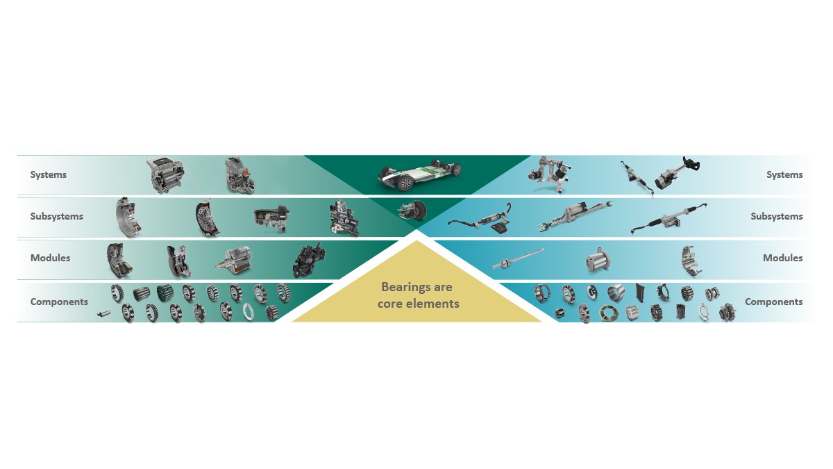
Current developments in the automotive sector are marked by an increasing degree of electrification of the powertrain. Schaeffler is driving these trends, for example, by developing electric axles and hybrid transmissions. The company’s extensive system and component know-how forms the foundation for this. It allows the individual components to be developed and coordinated in such a way that they contribute to functional improvements in their interplay within the system or make new solutions possible. A key component in the development of components in the electric system at Schaeffler is the rolling bearing, as shown in Figure 1. Its optimization requires a comprehensive overall system understanding in terms of both the bearing technology and the electrified powertrain systems. Schaeffler has been successfully represented on the market in both areas for many years and can draw on a wealth of specialized knowledge.
Development efforts in the field of battery-electric powertrains are currently focused on increasing the range and decreasing the charging times. If these requirements are transferred to the electric powertrain system development level, the following specific demands on the further development of the electric powertrain result:
- High electric motor speeds to enable lower electric motor mass
- Optimization of efficiency along the entire chain from electric motor to wheel
- Low mass through lightweight components
- High electrical voltage of up to 800 V for lower ohmic losses, faster charging, and use of smaller wire cross sections
- Low wheel bearing friction increases range.
In the implementation of all the above requirements, bearing development assumes a key role.
Bearings for high speeds
For reasons of mass reduction, more and more electric motors for electric vehicles are being designed for maximum speeds of 25,000 rpm, and even higher for some applications. These high-rpm electric motors are supported according to the state of the art with high-speed motor bearings (HSMBs) as shown in Figure 2 (in the upper left region of the gear diagram). This also applies to the transmission input shaft because it rotates at the same high speed that the rotor shaft rotates at; see Figure 2 (upper middle region of the gear diagram).
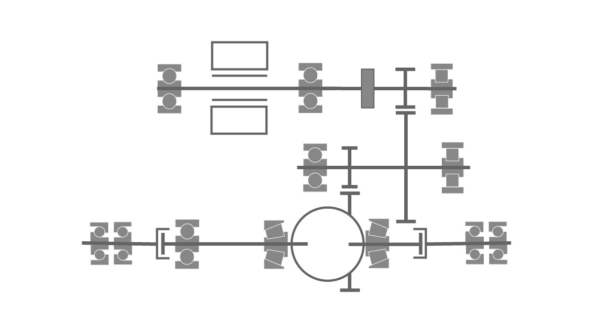
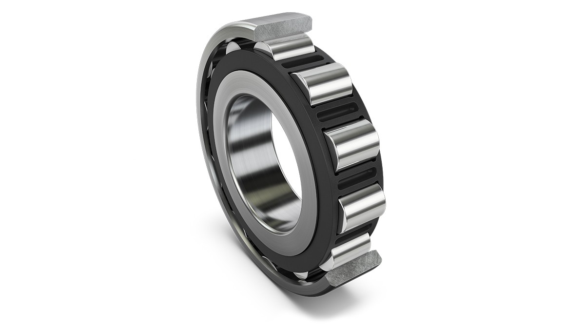
In most cases, an HSMB’s load capacity is sufficient for all occurring loads. However, for especially high-torque applications and/or if parking locks are used on the transmission input shaft, it is possible that the static load capacity of a ball bearing may no longer be sufficient. In this case, a high-speed cylindrical roller bearing offers a very good compromise between installation space and load capacity; see Figure 3.
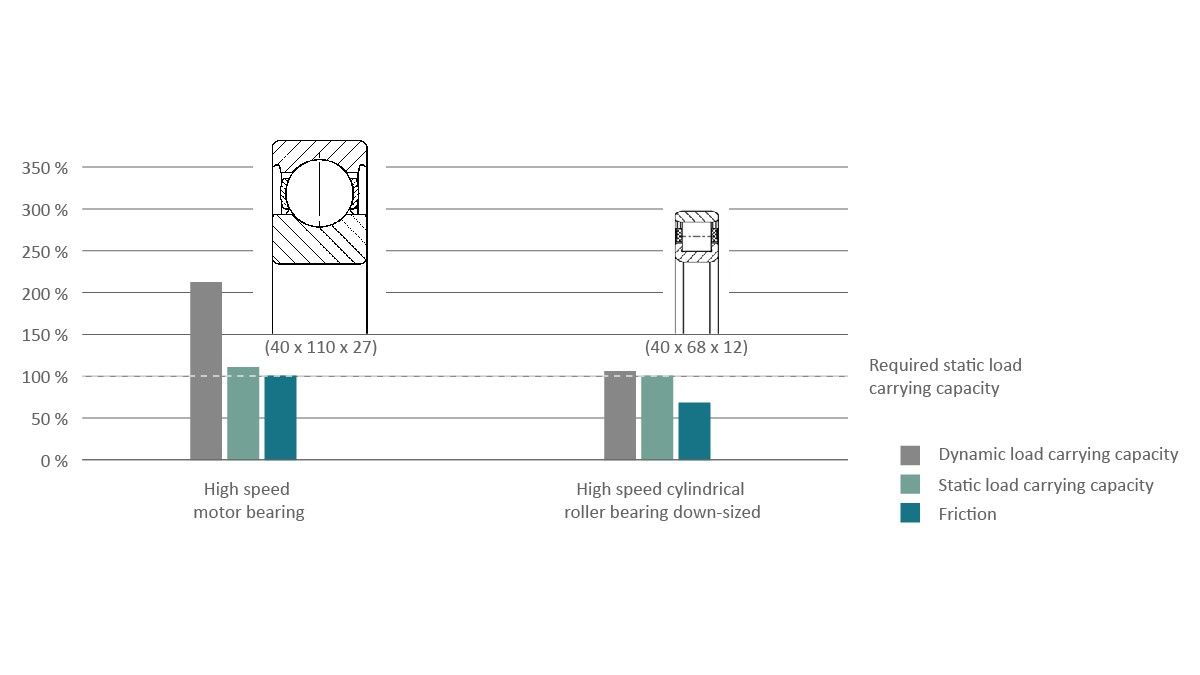
In contrast with conventional cylindrical roller bearings, high-speed roller bearings are optimized in terms of the internal profile, number of rolling elements, and dimensions as well as cage guidance and geometry [1]. Use of rolling elements with specially honed surfaces results in low noise levels. The N design with a flat outer ring and a double-flanged inner ring also makes it possible to minimize splash losses in the bearing and achieve speed parameters similar to those of the HSMB; see Figure 4.
This yields new possibilities for the development of future electric powertrains. For example, high-speed cylindrical roller bearings are being increasingly used on the transmission input shafts in electric axles. On the intermediate gear shaft shown in Figure 2 (in the middle region of the gear diagram), such a bearing can be used in combination with a ball bearing for a fixed-floating bearing arrangement to avoid preload-related friction losses as occur in adjusted bearing arrangements. In the case of a single-piece rotor-transmission input shaft, thanks to the new high-speed cylindrical roller bearings, electric motor supports will also be conceivable in the future as fixed-floating bearing arrangements with just one ball and one cylindrical roller bearing instead of today’s three or even four bearings.
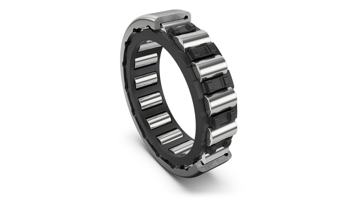
Further cost potential is offered here by a technology shift from cylindrical roller bearings manufactured as solid parts to drawn cup cylindrical roller bearings made from sheet metal. On this basis, Schaeffler can also present an economically attractive bearing arrangement concept for future high-performance electric axles; see Figure 5.
Efficiency-optimized bearings
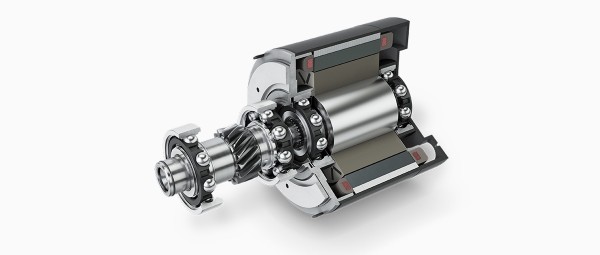
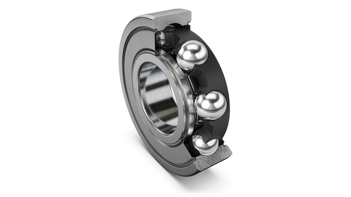
For applications in transmissions and intermediate shafts, Schaeffler has developed high-efficiency ball bearings with integrated patented centrifugal discs. The technology combines the benefits of both open-bearing and sealed-bearing designs. The centrifugal disc, which rotates with the inner ring, limits the amount of oil entering the bearing and thus reduces the splash losses; see Figure 6.
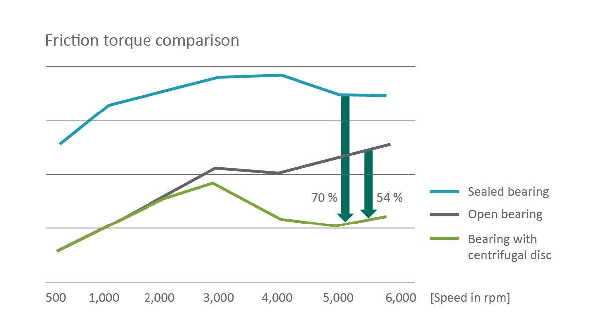
The disc effectively protects the bearing from contamination without causing any seal friction. A ball bearing equipped with this exhibits up to 70% less friction in operation than a sealed ball bearing and even up to 54% less than an open ball bearing, as shown in Figure 7.
Tapered roller bearings from Schaeffler have been used for decades in transmission output shafts and differentials. They are highly loadable and cover a wide power band. Due to their high effective bearing distance, tapered roller bearings can support high forces. With them, a clearance-free and stiff shaft guidance system is also possible. Through ongoing improvement of the bearing design and materials, Schaeffler has been able to achieve successive reductions in friction in the tapered roller bearings over the years, as Figure 8 shows.
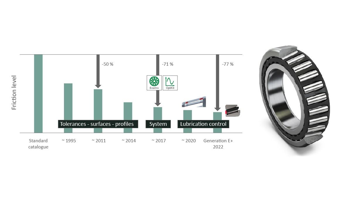
Generation C tapered roller bearings with X-life quality are widespread today. In order to fulfill the requirements of X-life, the geometry, surfaces, dimensional and running accuracy, and material and heat treatment were all optimized. Generation C tapered roller bearings are thus characterized by significantly smoother running and lower noise levels. In the improved Generation D, the flange opening angle and the roller–flange contact were optimized. With Generation D+, Schaeffler achieved another significant reduction in friction through application-specific optimization using the OptiKit computational tool developed in-house. New approaches for realizing further improvements in efficiency are offered by Generation E with revised roller butting contacts and Generation E+ with integrated oil separation through the corresponding structural design of the cage. Generation E+ reduces friction by 77% compared with a standard tapered roller bearing. In addition, the Durotect B chemical surface treatment offers further potential for friction reduction in all tapered roller bearing generations.
High-voltage applications
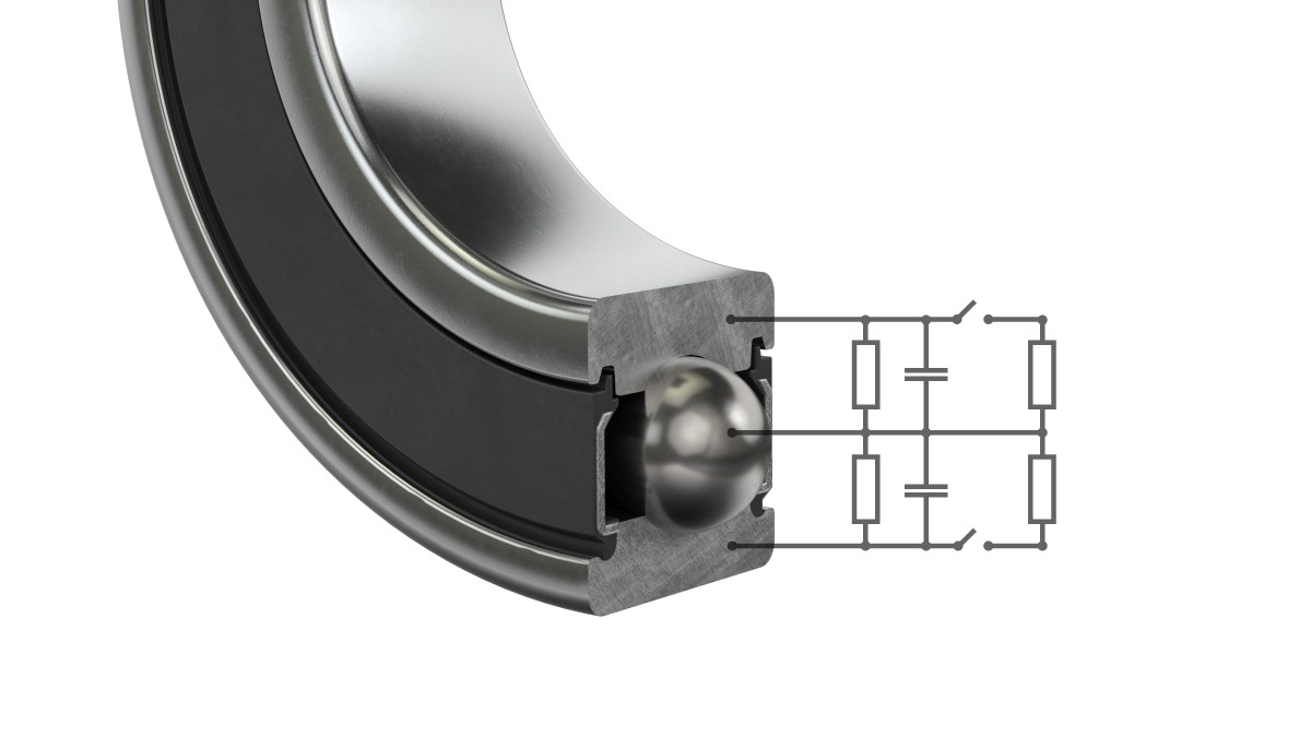
If rolling bearings are used in high-voltage electric motors, a purely mechanical consideration of the operating conditions is no longer sufficient for the system design. In this case, the bearings must also be assessed with regard to their electrical properties, as shown in Figure 9. The working principle of the bearing can be described in a simplified manner using the equivalent circuit diagram of capacitors and resistors shown in Figure 10.
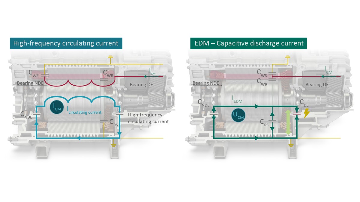
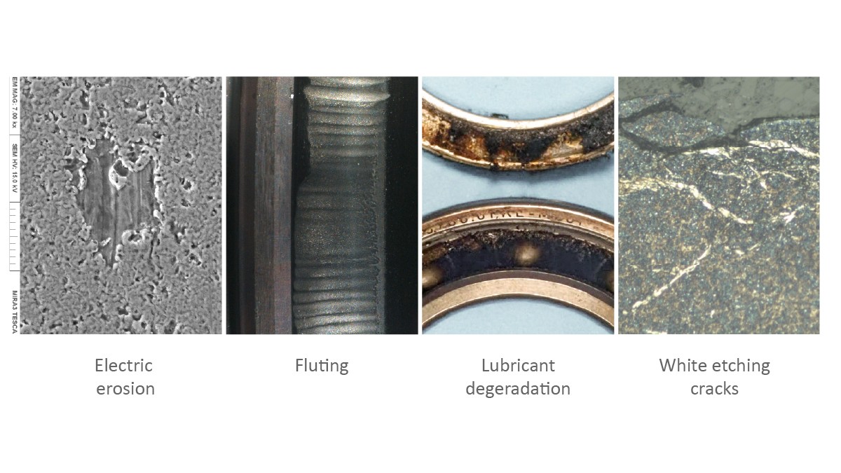
The resistances depend on the given lubrication conditions and can change from high values in the case of full lubrication to almost zero in the case of mixed friction conditions. Uncontrolled discharge currents can cause bearing failure. Typical damage includes electrical erosion of the metal surfaces, fluting of the bearing raceways, aging of the lubricant, and cracks in the microstructure of the bearing steel (white etching cracks, or “WEC”); see Figure 11. The risk of electromagnetic interference due to the discharge currents is another problem. If the electrical characteristics of the powertrain system are known, the electrical loads on the bearings can be calculated and design countermeasures can be implemented in the bearing development phase. Depending on the respective application, approaches utilizing current shunt, current insulation, or a combination of the two are used, as shown in Figure 9.
Current shunt
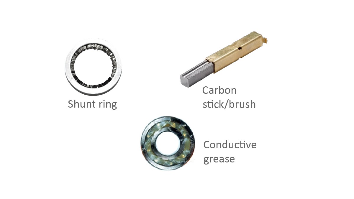
For a defined discharge current (current shunt) to be generated, a continuous and functionally reliable electrical connection between the inner and the outer ring of the bearing or between the shaft and the outer bearing housing must be guaranteed. The solutions currently available include slip rings (shunt rings) or pickups such as carbon pins or brushes that run on the shaft; see Figure 12. They all have the disadvantage of having to be integrated into the motor design as an additional add-on part and mounted when the powertrain is assembled. Some are only effective in dry environments, not in the oil circuit. Another possibility is offered by special conductive greases in the bearings, which, however, negatively affect the bearing friction and can result in conductive material becoming distributed in the motor compartment as the grease is flushed out.
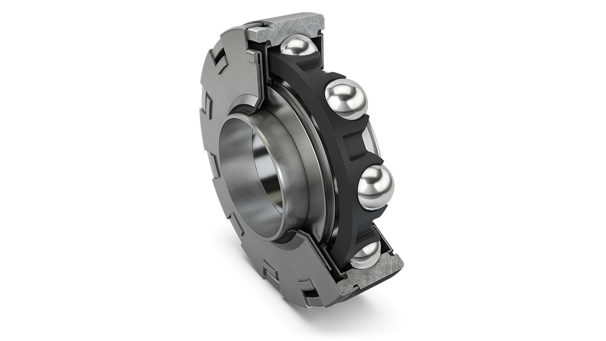
Schaeffler is currently developing a high-speed motor bearing with an integrated shunt element, as shown in Figure 13. It is based on a high-speed motor bearing. The inner ring of the bearing has a coated sleeve, which the shunt element contacts. Integration of the shunt function into the rotor bearing conducts the current away from the places where potential electrically induced damage could occur. In the design of the sliding electrical contact, a balance must be struck between increased friction and wear on one hand and reliable conduction under all operating conditions on the other hand. At the current state of development, the bearing offers, apart from an additional axial installation space requirement of just 5 mm, a high speed stability of up to 20,000 rpm. When the powertrain is assembled, only one component for both functions needs to be mounted, so motor production requires less effort and is less complex.
Current insulation
Bearings with electrical insulation properties (current insulation) are usually designed today either as hybrid bearings with ceramic balls or with ceramic coatings; see Figure 14.
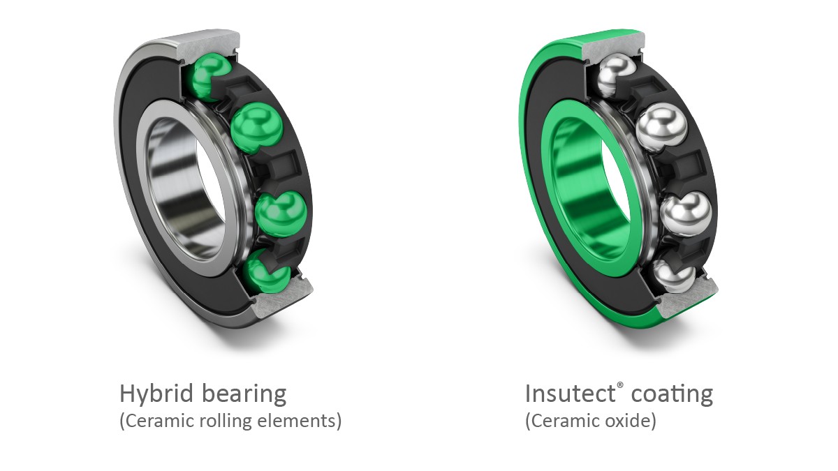
Both of these implementations are associated with additional costs. Due to the expensive ceramic rolling elements, a hybrid bearing costs up to five times as much as a conventional high-speed motor bearing does. At the same time, the higher Young’s modulus of the ceramic balls leads to higher pressures at the raceway contact areas for the same external loads. The ceramic outer ring coating, which is several tenths of a millimeter thick and applied using a plasma spray process, requires additional subsequent grinding of the outer ring diameter.
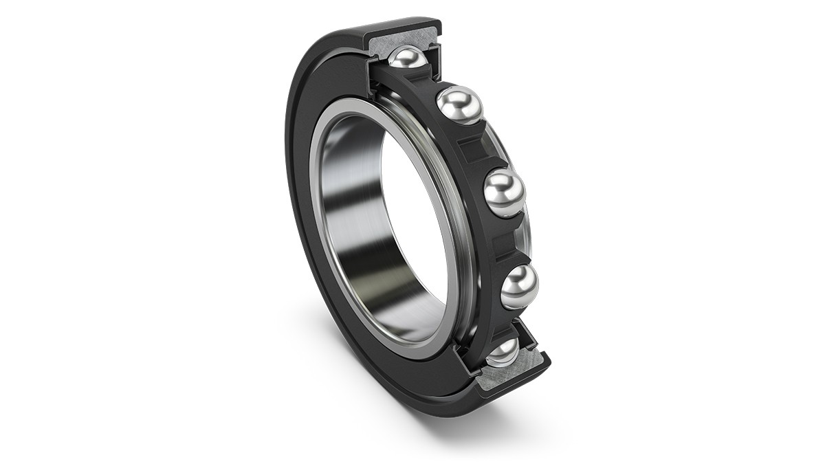
A new insulation concept from Schaeffler offers equally effective insulation properties at significantly lower costs. The outer ring is overmolded with a plastic as shown in Figure 15. The thermosetting plastic used provides high mechanical and chemical resistance up to temperatures of 150 °C. The insulated bearings also offer mechanical properties similar to those of conventional rolling bearings, for example, in terms of stiffness, dimensional accuracy, load capacity, and speed stability, and are suitable for both dry and oil-lubricated environmental conditions. The normal bearings can often simply be replaced without any design changes to the shaft or bearing housing being required.
Mass and friction reduction
Wheel bearings offer the potential for further reductions in mass and friction. Depending on the application, the design weighting can be on one or the other parameter. In order to meet the different requirements, Schaeffler organized the wheel bearing development process into three segments as shown in Figure 16:
- Double-row wheel bearing units for low friction
- Wheel bearing units with face spline designs for higher torque transmission
- riple-row bearings for high loads
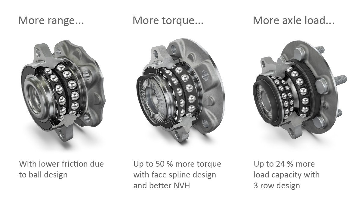
The friction-optimized wheel bearing shown on the left in Figure 16 offers an up to 50% reduction in friction compared with standard solutions. For the example of a vehicle application with an internal combustion engine, CO2 savings of 0.44 g/km are achieved; for an electric powertrain, a 0.6% reduction in electrical energy requirements can be achieved. These improvements are achieved through an optimized seal design, innovative bearing grease, and an improved internal design.
The clearance-free face spline design shown in Figure 16 (middle) enables transmission of up to 50% more drive torque with a lower weight, easier mounting, and less noise with the same dimensions. This is especially important in electric vehicles.
With TriFinity, Schaeffler offers a triple-row wheel bearing, as shown in Figure 16 (right), that is intended for use in electric powertrains. Compared with a standard double-row ball bearing, the TriFinity bearing can transmit higher axial loads while offering a significantly longer service life and improved stiffness without a change in bearing dimensions. Moreover, this innovative ball bearing concept can replace preloaded tapered roller bearing units. Switching from the bearing technology with tapered rollers to balls leads to significant improvements in frictional torque and stiffness, resulting in 0.7% energy savings per vehicle in the FTP75 cycle. Wheel bearing units with smaller diameters can be realized with the TriFinity bearing as a downsizing solution in combination with the Schaeffler face spline design. This leads to less bearing and seal friction, optimized bearing weight, and lower CO2 emissions.
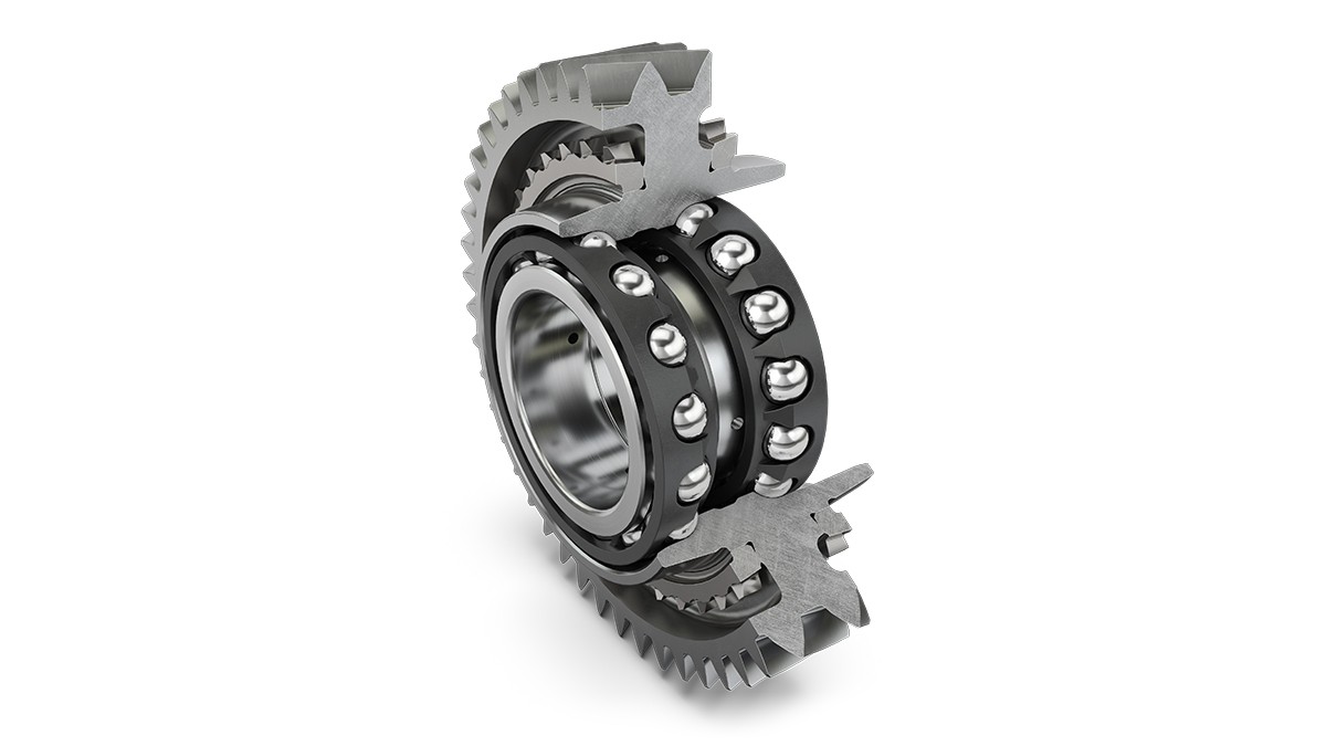
Another approach for reducing weight is to use bearings that are integrated into the gear wheels as shown in Figure 17. The outer ring of the rolling bearing is not pressed in, but is formed from the gear material. This eliminates the need for a separate outer bearing ring and thus saves on material and mounting efforts by the customer. At the same time, larger pitch circle diameters and/or larger rolling elements allow for higher load ratings, and the bearing is also smaller overall. According to the current planning status, mass production of the gear bearing unit will start in 2022.
Simulation-based development
The right design of a bearing for the individual requirements of the application begins in the conceptualization phase for the overall system. If the bearing, including all load collectives and operating conditions, is taken into account right from the start in the design and dimensioning of the components, subsequent design changes, which are often associated with considerable time expenditures and costs, can be effectively prevented. Calculations form the main pillar of this so-called frontloading concept. Schaeffler offers a comprehensive chain of simulation tools that support the entire development process.
The BearinX Simulation Suite developed by Schaeffler comprises the program modules Simpla, BearinX, Caba3D, and Telos. Simpla uses a hybrid multibody simulation (MBS) with a nonlinear, multidimensionally coupled bearing model to reproduce the dynamic behavior of the complete system. The MKS model can be derived from the existing BearinX software models. With BearinX, all bearing types, complex shafts, and shaft systems up to complete transmissions can be simulated and calculated. Among other things, bearing stiffnesses, shaft elasticities, axles, the housing and the environment, bearing operating clearances or preloads, roller and raceway profiles, raceway lubrication, and the actual contact pressure are taken into account. The fatigue life calculation is also integrated in BearinX. The software tool Caba3D enables the dynamic analysis of rolling bearings, for example, by determining the rolling element and ring forces and their movements and by calculating the dynamic cage behavior, the power loss due to friction, and the acceleration behavior of the rolling elements. The 3D simulation program Telos calculates rolling contacts under general lubrication conditions and under quasi-static and transient loads. Telos is suitable for bearing components with and without coatings.
Ever since the first version of the BearinX software was developed in 1997 – making it possible for the first time ever to calculate an exact bearing down to the individual rolling element contact – Schaeffler has been using the constantly updated BearinX Simulation Suite as the standard for all bearing developments.
Summary
Current developments in the automotive sector are marked by an increasing degree of electrification of the powertrain. Development efforts in the field of battery-electric powertrains are currently focused on increasing the range and decreasing the charging times. This results in specific demands on the electric powertrain system, including reduction of masses and power losses, increase in maximum speed of the electric motors, and increase in system voltage to up to 800 V. Rolling bearings assume a key role here because they decisively contribute to improving the functioning of the electric powertrain and make new technical solutions possible. Using a comprehensive chain of simulation tools, Schaeffler is successively developing the bearing technology as a module in the system development to be able to offer optimal solutions for different requirements.
An example of a bearing with high speed capability is a new roller bearing that combines the high-speed properties of high-speed motor bearings with the load capacity of conventional roller bearings. Further efficiency improvements are offered by innovative high-performance ball bearings with centrifugal discs. The disc limits the amount of oil entering the bearing and thus reduces splash losses and effectively protects the bearing from contamination without causing any seal friction. To reduce the mass of the wheel bearings, Schaeffler makes use of the design possibilities of bearing arrangements that were conceptualized for high loads in order to enable weight-saving component downsizing. The reduced mass and lowered friction lead to a greater range in battery-electric vehicles. High-voltage systems with vehicle electrical system voltages of up to 800 V or power electronics based on silicon carbide (SiC) impose very specific requirements on the bearings of electric motors. During operation, discharge currents can arise and pose a risk of failure. Schaeffler addresses this phenomenon with concepts for either defined current shunt or effective insulation of the currents to avoid electrically induced damage to the bearings and gear parts. With this mixture of innovation and evolutionary development, Schaeffler keeps rolling bearings at the cutting edge of technology – and thus constantly reinvents them.
[1] Völkel, F., et al.: Rolling into the Future – Bearing Solutions for Electric Mobility. 20th International VDI Congress “Dritev – Drivetrain for Vehicles,” 2020.