Next-Generation Actuator Systems
Mathias Göckler | Peter Biegert | Marco Grethel
Intelligent actuator technologies are becoming increasingly important in efficient powertrains for setting the optimum operating condition for each specific driving situation. While electromechanical actuators are the best solution for individual or distributed actuation tasks, hydraulic actuator systems enable the implementation of complex control architectures including temperature control and lubrication functions. Schaeffler supplies innovative actuator system solutions which meet the specific functional requirements of the powertrain and its architecture. To be able to react flexibly, quickly, and economically to new application requirements, Schaeffler is developing a smart hydraulic kit which includes software elements, hardware components, and production technologies and thus covers the entire added value chain from conception to production. At the same time, Schaeffler is also taking electromechanical actuators to the next level and its range includes a comprehensive set of different solutions for various actuation tasks.
Actuator tasks
The main task of an actuator in a powertrain is to set the optimum operating point to best suit the actual driving situation. For example, in a dedicated hybrid transmission, this can be switching between parallel and serial mode or, in an e-axle, it can also be to engage the parking lock to ensure the vehicle is at a safe standstill. However, the optimum operating point in modern drives is achieved not only through adjusting the drive mode but also through ensuring optimum temperature and lubrication conditions within the powertrain. The high efficiency of modern powertrains and their very low levels of available heat loss means this thermal energy must be harvested and distributed more intelligently. Optimum thermal conditions are to be created in the drive at both low and high temperatures and heat is to be transmitted to specific areas of the vehicle.
Thus, the actuator hydraulics must, on the one hand, provide the energy to operate the slave element(s) and, on the other hand, ensure distribution of the oil for temperature control and lubrication purposes. Key areas in the development of actuator hydraulics are a simple construction and minimal overall power consumption resulting in high cost-effectiveness. The sub-functions have to be carefully harmonized during development so that the actuation system ensures maximum efficiency and optimum driving comfort at the vehicle level. The modular hydraulic system from Schaeffler covers the requirements of a range of powertrain architectures from a simple design to complexes structures.
Alternatively, an electromechanical actuator can be used instead of an oil-actuated design. Schaeffler has a comprehensive set of different solutions in its range here as well. The more diverse and numerous the tasks of the actuator in the transmission, the greater the benefits of a hydraulic system with central pressure generation and distribution to the individual slave elements.
Influences on actuator technologies
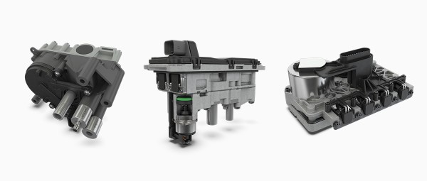
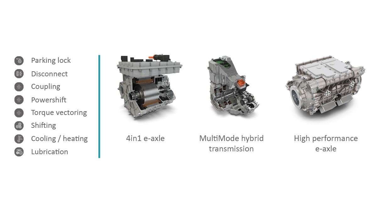
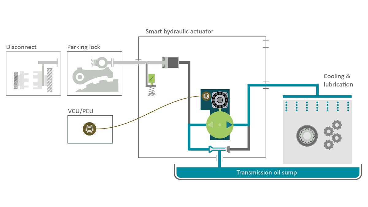
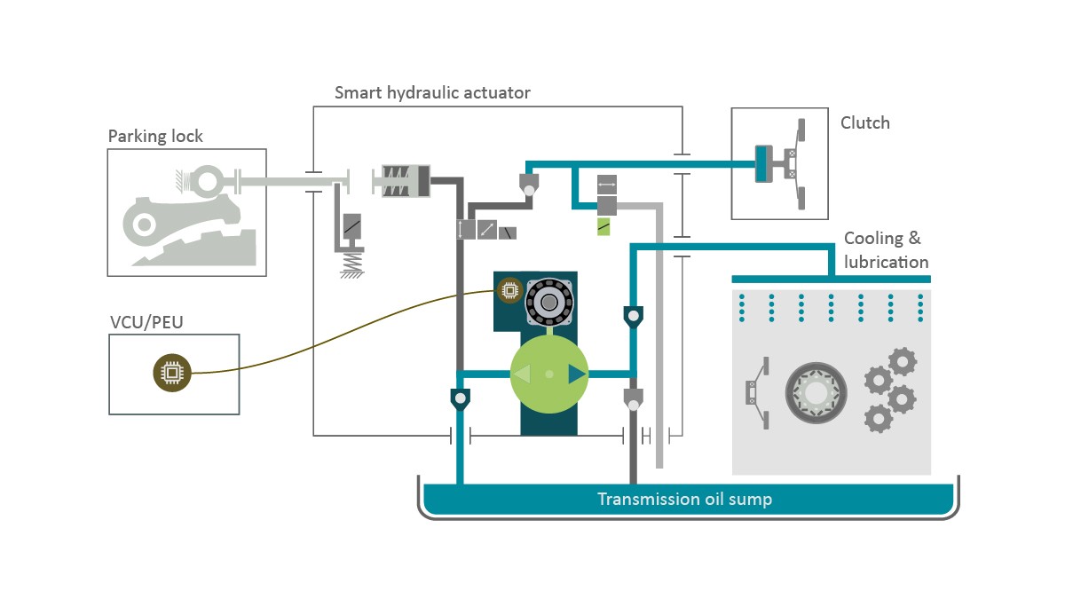
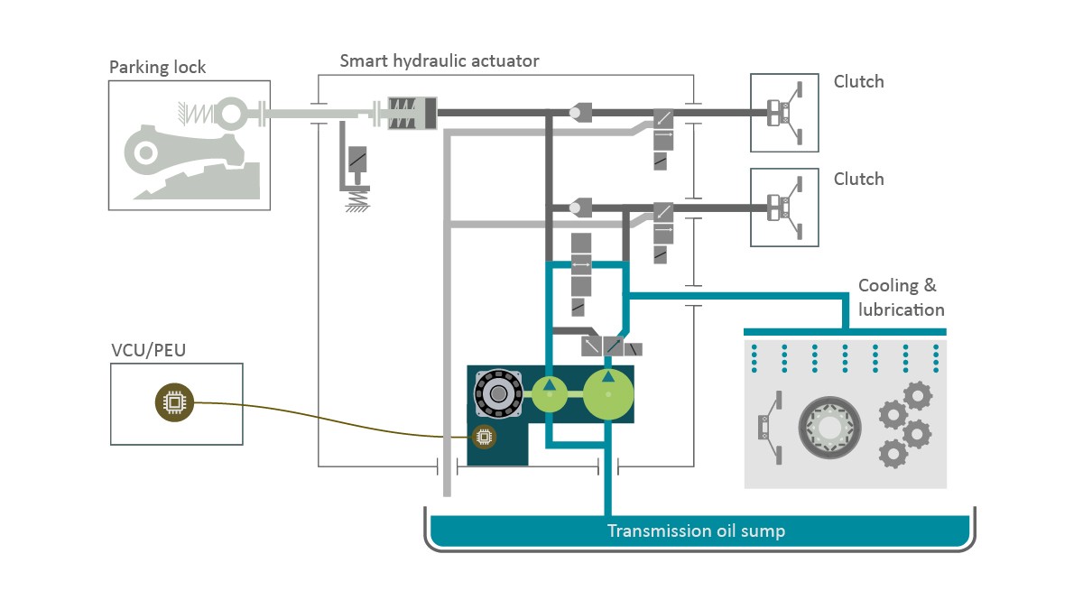
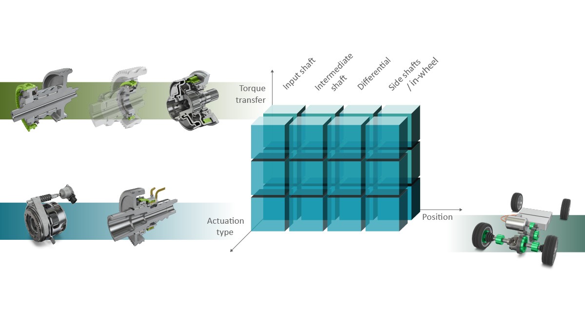
The demands on hydraulic actuators and their potential functions vary depending on the powertrains in which they are used [1]. In a simple transmission in an e-axle, in addition to the required oil lubrication and cooling, there is typically just one shifting function, for example, the hydraulic parking lock on the primary e-axle, or the disconnect unit on the secondary e-axle, Figure 1. A dedicated hybrid transmission, such as the Schaeffler MultiMode hybrid transmission [2, 3], also includes operating a slave element such as a separating clutch. Particularly complex powertrain structures, such as the high-performance e-axle with additional powershift multi-speed capabilities or wheel-selective torque vectoring, use several very different slave elements to control the functions in parallel [4].
Hydraulic actuator architecture functions
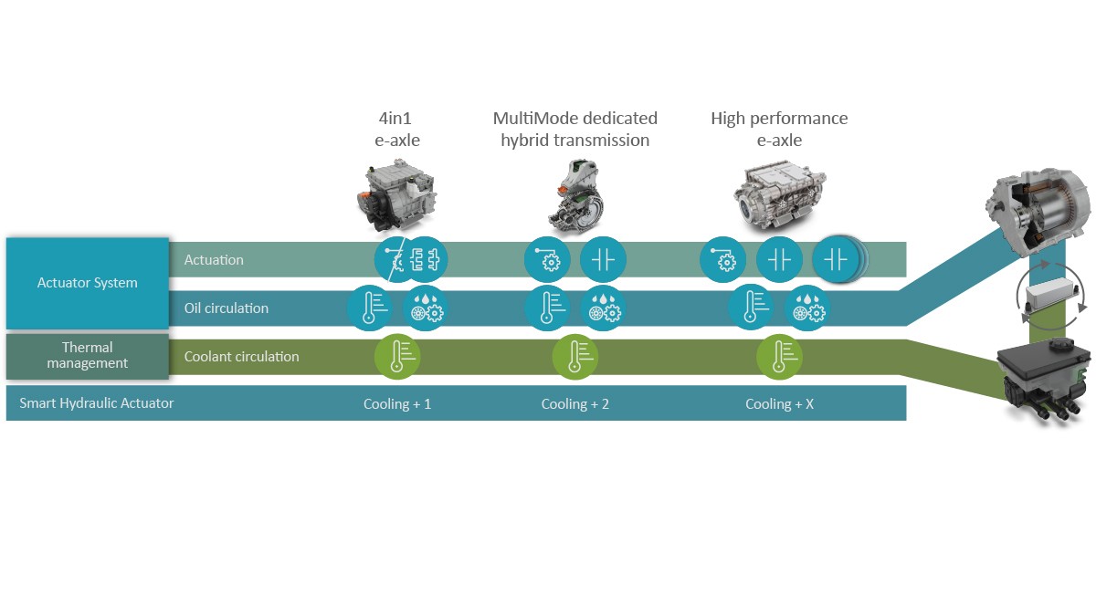
The actuation systems in the various powertrain architectures all have to provide the required oil circulation for the temperature-control and lubrication functions in addition to the actuation functions. Figure 2 shows the increasing actuation requirement from left to right starting with one additional function (cooling + 1), through two additional functions (cooling + 2), to several functions which can be controlled in parallel (cooling + x). The oil circulation function for the lubrication and the cooling and heating of the transmission typically define the required continuous power of the system. The actuation functions, on the other hand, have only a short power requirement (peak power) during the actuating process. In a constant driving situation, there are therefore preferably no continuous power demands on the slave elements.
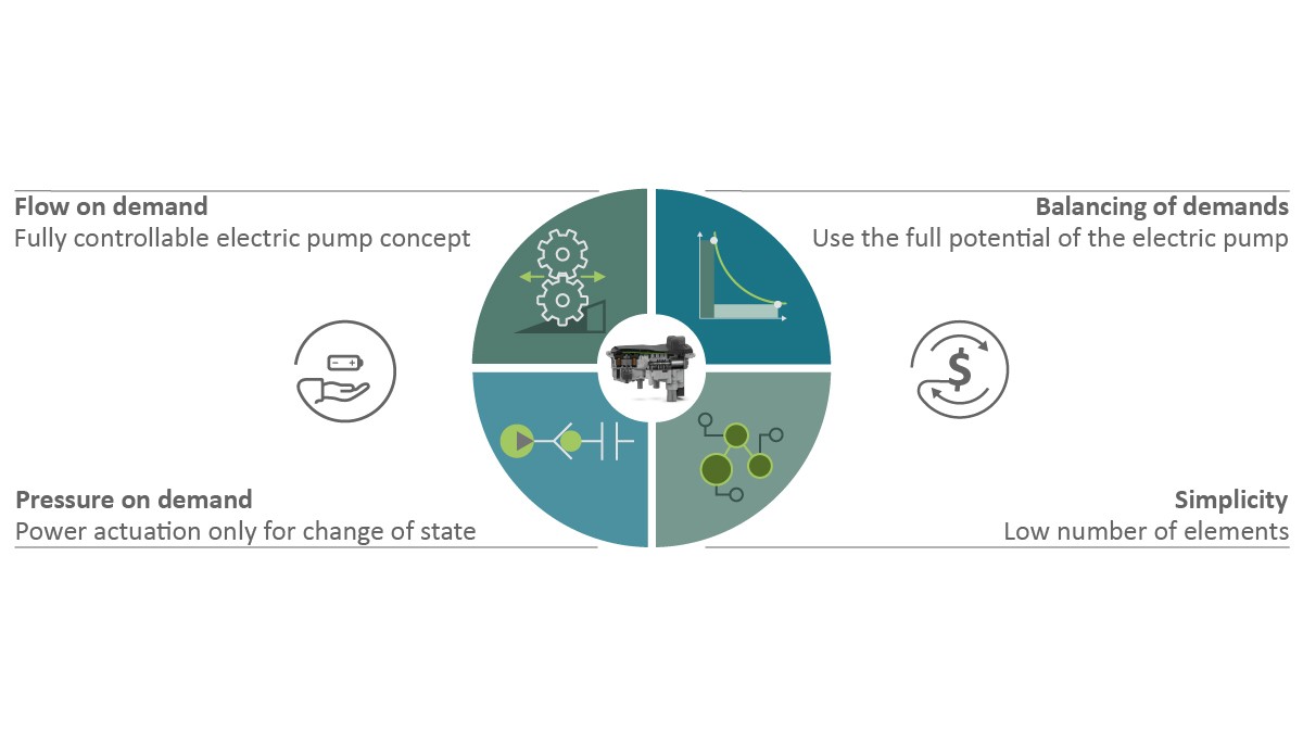
When the combination and number of the consumers are taken into consideration, a suitable actuator system architecture must be found when developing the powertrain system which combines low power demand with a simple design. These two characteristics are the basis of the high efficiency of the overall system. Four basic premises for the hydraulic architecture can be derived from this, Figure 3:
- Volume Flow on Demand – fully demand-based and therefore efficient oil supply to provide optimum temperature control as requested by the thermal management system.
- Pressure on Demand – the slave elements are disconnected during steady driving situations and therefore do not consume any energy in order to achieve optimum efficiency in the relevant cycles
- Balancing of Demands – in order to dimension the system as cost-effectively as possible, the peak power demands of each consumer are harmonized and optimum use is therefore made of the drive
- Simplicity – straightforward design leads to fewer components and interfaces and therefore to lower development and system costs.
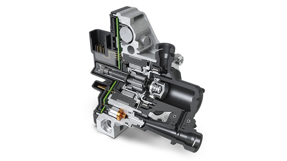
The principle of reversing, as demonstrated in the electric pump actuator (EPA), has already been presented at the Schaeffler Colloquium, 2018 [1, 5]. Schaeffler has developed the technology further in recent years and is now using it for the smart hydraulic actuator (SHA) product family. A wide range of hydraulic architectures with a scalable range of functions can be quickly and easily derived from the existing modular system. In the most straightforward transmission concept, the ‘cooling + 1’ actuator, the two tasks of circulating heat and operating the slave element are quite simply implemented without the use of active valves by reversing the pump direction, Figure 4. The two-pressure valve allows the pump to prime from both directions and shut off the opposing side. Rotation in one direction operates the cooling function while rotation in the opposite direction operates the actuator piston. A mechanism which can be designed to be stable in either the final position or a specific position locates the actuator piston. This means that the pump is once again fully available for the cooling function once the actuator piston has been operated.
The addition of a third actuating function (cooling + 2) makes life somewhat more difficult. The SHA, Figure 5, provides a solution with minimal complexity. However, an active valve is required which switches the oil pressure during reversing, directing it to one slave element or the other.
A passive two-pressure valve or two check valves on the suction side in the SHA allow a sequential build-up of pressure at the pump’s two working connections. This means that the SHA applies pressure to a consumer, such as a clutch, in the initial direction of rotation. This closes the clutch as required. As shown in the functional sketch, Figure 6, a check valve then maintains the pressure in the clutch so that the SHA can cool using the pump’s secondary direction of rotation. If the pressure in the clutch falls below a threshold value, the cooling is briefly interrupted. The pump rotates in the opposite direction in order to increase the pressure in the clutch again. The drain valve is used to open the clutch as required; it is not necessary to reverse the direction of rotation of the pump to do this. Using the capacity of the clutch as a pressure accumulator is an example of using a ‘pressure on demand’ approach when developing the actuator system. In some applications, for example, a parking lock on electric vehicles, it is necessary to lock the actuator in its final position if the parking lock is to be engaged passively. This can be achieved using an electromagnet which, however, generates a certain permanent energy demand, or a kinematic locking function which is controlled by the oil flow.
The parallel actuation of completely controllable functions, such as for clutches, requires an alternative concept but one which must still follow the four basic premises laid out above, i.e. the ‘cooling + x’ architecture, Figure 7. Here, the basic architecture is not limited to this application but can be scaled on a modular basis and adapted to many other powertrain systems.
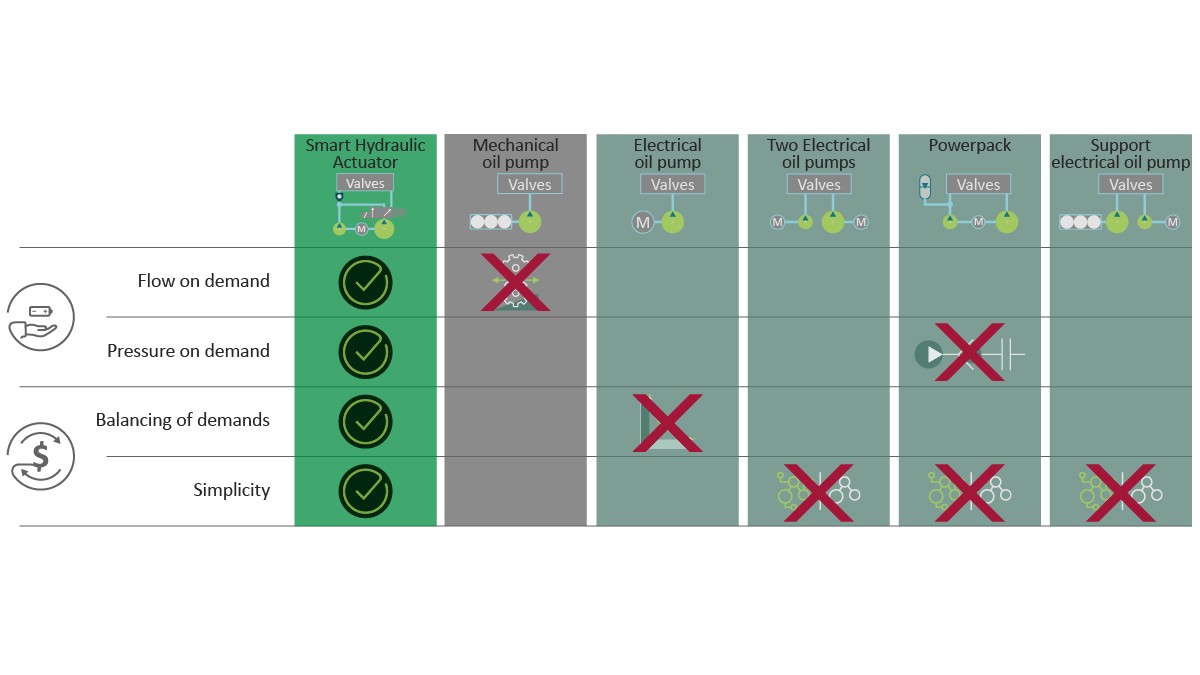
Possible alternative configurations of the actuation system required for a powershift e-axle would be a mechanical pump with or without electric support or a purely electric pump solution with or without a pressure accumulator. These can be designed with either one or two pumps, each with its own e-motor, or as a tandem system with just one drive, Figure 8. As the benchmark comparison shows, the concept pursued by Schaeffler, a combination of a tandem pump arrangement and electric valves, meets all the hydraulic system's requirements. Compared to the other approaches, Schaeffler’s basic architecture achieves greater efficiency with less complexity and therefore lower costs. The key to success lies in the dimensioning of the tandem pump combined with the boost valve and an innovative control system. Here, the actuator supply pump is designed with as low a volume as possible, with the primary aim of ensuring the slave elements receive the base supply levels. This allows small volumes of pressurized oil to be discharged into the cooling oil circuit over extended periods of time via the system pressure regulator. If a high flow rate volume is required in the actuation circuit for a short period of time, for example when filling a clutch, the boost valve also feeds the cooling oil volume flow. The cooling oil pump is therefore put under high pressure for only a very short period of time. Appropriate control of the boost valve and the pump drive thus allows the demands on the dynamics to be achieved with an extremely low power consumption during driving.
Power consumption analysis
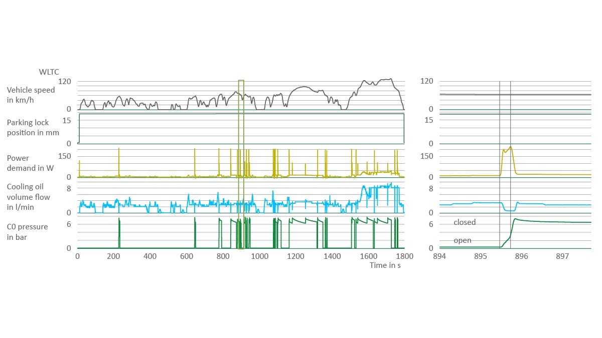
Figure 9 shows extracts from the measured results for the power consumption in a ‘cooling + 2’ SHA in the driving cycle (white line) for the current WLTP (Worldwide harmonized Light vehicles Test Procedure) valid in Europe in a serial-parallel hybrid drive. The power consumption of the hydraulic pump over the complete cycle is decisively determined by the cooling oil flow requirement in the powertrain (blue line). As driving commences, the parking lock is disengaged once and has no further power demand after that (light green line). During driving, short clutch actuation power peaks occur due to coupling events(green line). The transmission cooling is simultaneously briefly interrupted in order to control the clutch. This process has no significant effect on the thermal system but instead ensures excessive peak loads are avoided. The total power demand line also shows this (yellow line). Excessively high load peaks would have to be taken into consideration in the design and would have negative effects on the hydraulic system's dimensioning.
To show these reciprocal processes more clearly, the gray area in the diagram on the left is shown in more detail on the right with an expanded time axis. Here, it is easy to see that the switching procedure for the separating clutch does, in fact, lead to a brief increase in the output. However, this effect is compensated by a brief drop in the cooling oil supply. The energy requirement for the slave element is also only a short pulse. This has effectively no impact on the overall energy consumption and therefore on the measured CO2 emissions for the WLTP. Over the complete cycle, the actuator system on average required only 12 W of electrical power. This value is less than many dedicated power-on-demand actuators on the market.
Software and hardware kit
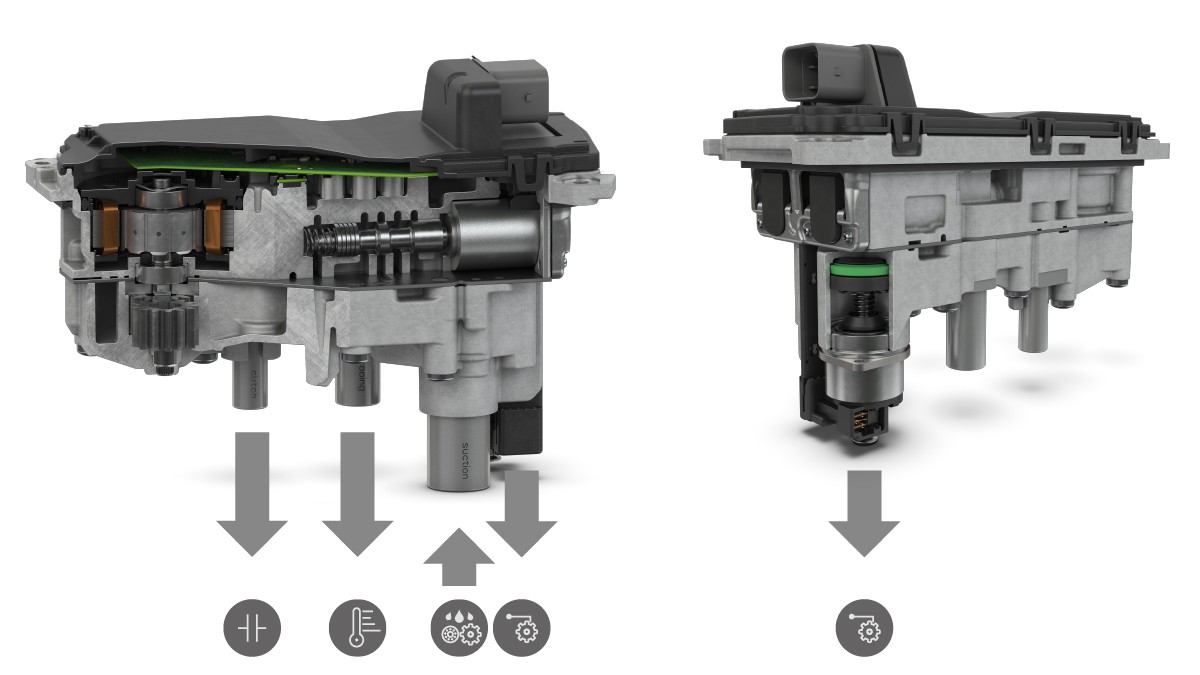
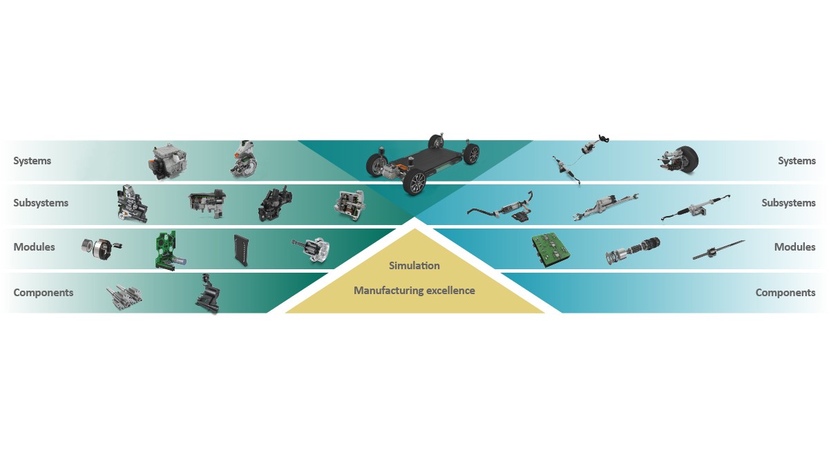
When expenditure on the actuator is considered, the costs for designing, testing and producing the components as well as integrating them into the overall system must be taken into consideration in addition to their operating costs. Savings in these areas can be achieved on three levels: By reusing standardized software components, by using previously developed hardware components, and with the aid of shared production processes. In order to be able to react flexibly, quickly, and cost-effectively to new application requirements, Schaeffler has based the SHA on the modular actuation system which offers standardized solutions on both the software and hardware sides, Figure 10. By taking a platform-based approach which extends across projects and customers with maximum potential for reuse, the number of variants can be reduced which has a positive influence on component manufacturing.
Experience with developing series software, which has grown over recent decades, shows that this takes up a significant proportion of the development work. The reasons for this include the extremely complex demands on the software and the extensive documentation, as well as the rapidly expanding requirements in the fields of functional safety and cyber security.
The software is an integral component of the actuation technology and its various elements cover all functional levels, from control of the entire system to individual components. For this reason, the software itself has a modular structure on the different levels. To put it simply, application-specific functions can be achieved on the upper software levels by using basic software modules to meet the particular demands of the various SHA architectures.
To facilitate use of software as a modular solution, the hardware must have a uniform technical basis. Only by using identical or at least comparable concepts for the motors, kinematics and sensors across multiple actuators in the modular system is it possible to deploy software components more than once and therefore to significantly reduce the cost of programming.
Schaeffler has always considered a high level of vertical integration and the development of in-house production processes to be key components of the company’s success. A modular production plant concept and the close cooperation between the prototype shop and mass production allow rapid transfer of new technologies into serial production and a flexible scaling of production capacities. This gives the business the capacity to react dynamically to changing market conditions.
This know-how is backed up by holistic system expertise in the fields of electronics and powertrains which has grown and been consistently built up over decades, supplemented by strategic acquisitions. As a result, Schaeffler is now able to develop and produce e-motors of all sizes in-house, from small actuator drives to large traction motors for electric battery-operated vehicles. For example, the vertical production integration for the brushless e-motors in the actuators extends from the stamped stator sheets, through the winding, to the final overmolding of the stator and rotor.
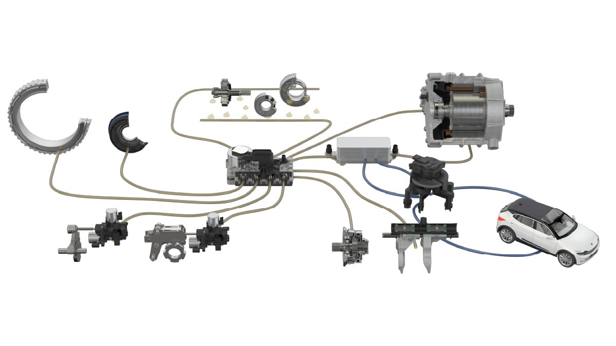
Functional integration is based on a holistic understanding of the entire powertrain which allows an appropriate actuator system architecture to be derived from customers’ requirements and the software and hardware solutions from the SHA modular system to be tailored to this, Figure 11.
Design example - e-axle disconnecting module
One example of determining the optimum architecture based on Schaeffler's detailed understanding of the entire system and the many different options provided by the SHA modular system is the integration of the disconnecting module into the flow of forces in an e-axle. The option of a mechanical disconnection usually only makes sense if the e-axle is used as a secondary drive to represent an all-wheel drive. This can be either as an electrical component in a hybridization (P4 hybrid) or as a component in a purely electrical system. The main consideration when deciding on the integration of a disconnection unit are the induction and friction losses caused by the e-axle while its additional output is not needed. In fact, these can be reduced through the choice of motor concept used but not the friction and churning losses from the gears.
In a typical application in a mid-range electric vehicle with two 150 kW e-axles and a 60 kWh battery the secondary drive is not used effectively over 83 % of the duration of WLTP cycle. If one of the electric drives is disconnected over this period of time, an energy saving of approximately 4.5 % is achieved over the cycle. If larger-sized electric drives are chosen for sports applications, the connected time period is even less leading to a potential saving of up to 10 %.
When choosing the best disconnecting module for an application, the starting point is often defining its position in the powertrain. When considering which disconnecting concept is most appropriate for the particular use of the e-axle, the overall system architecture must be taken into account. To put it simply, it is possible to say that the most significant effect is derived from disconnecting the e-motor. The positive effects on the friction increase further the closer the disconnection point is to the wheels as fewer and fewer components such as gears are driven by the wheels in the disconnected condition. However, the torque levels also increase with the proximity to the wheels, as do the integration effort and costs.
Electromechanical actuators
If there is no requirement for oil to circulate from the hydraulic system to control the temperature and lubricate the transmission, or less complex or distributed actuator tasks are to be implemented, the use of an electromechanical actuator instead of a hydraulic actuator is an option. Schaeffler is continuing to develop this technology and is extending the modular system further. The modular clutch actuator, MCA was presented as an actuator concept at the Schaeffler Colloquium, 2018 [1, 6], Figure 13.
This concept focuses on modularity and easy system integration. The MCA is therefore suitable, for example, for fully automatic clutches in hybridized manual transmissions (electronic clutch management, ECM) and for clutch-by-wire systems. The brushless electric motor, the electronic controller, and the compact planetary roller screw make up the core of the actuator. Unlike other concepts in which the position is expensively recorded using an absolute position sensor, the MCA has an angular position sensor with its own memory. The specific friction on the wrap spring in the actuator [6] when traveling forwards and backwards allows self-retaining behavior, i.e. power on demand, while maintaining very high dynamics. The MCA also has system integration options as it can be equipped with a hydrostatic or mechanical interface. The built-in electronics offer high processing power even for demanding control tasks and have additional inputs for external sensors. The modular ‘all-in-one’ concept of the MCA makes integration easier, increases its robustness, and improves the efficiency and performance capability of the actuator. The MCA concept presented in 2018 went into serial production in 2020. The concept’s high flexibility, performance capability, and reliability is also demonstrated in motor sports projects that Schaeffler has been implementing since the start of 2021 with motor sports partners such as BMW in the M4 GT3.
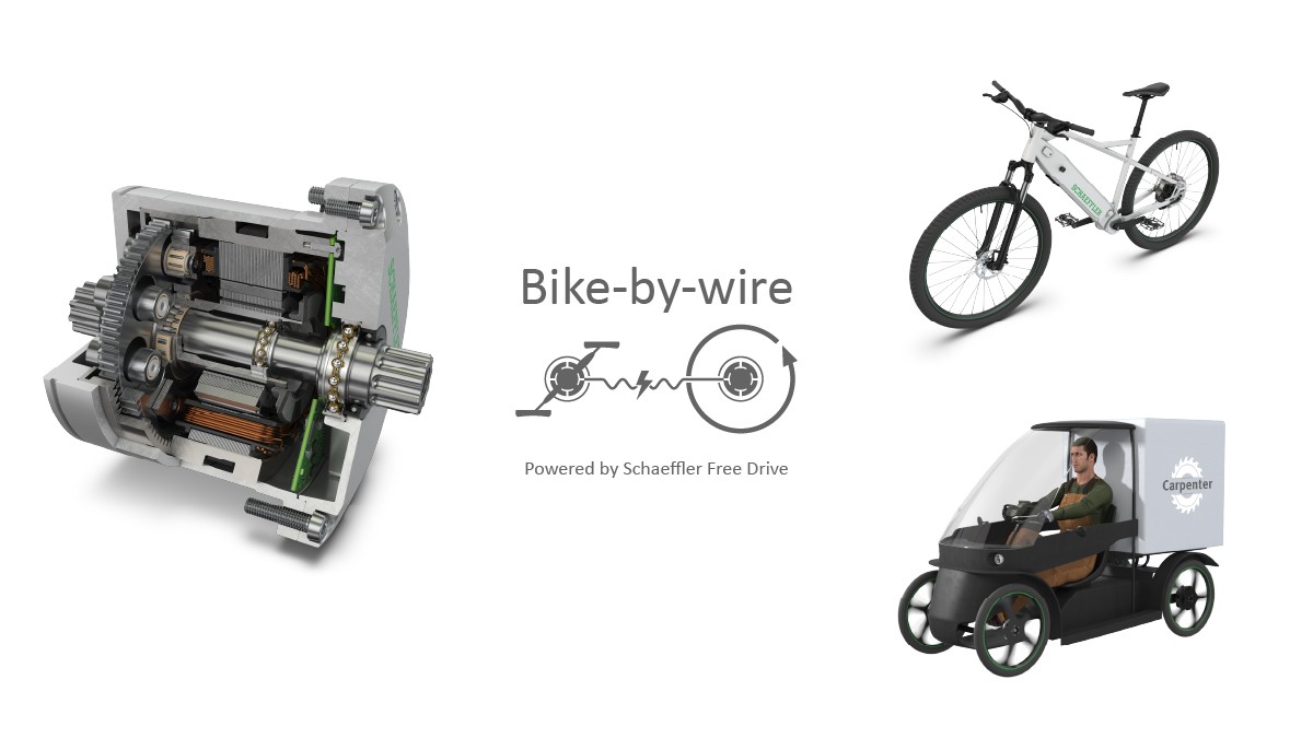
Pedal-driven generator for micromobility concepts
A further pioneering application for Schaeffler's innovative actuator technology can be found in the field of micromobility in the urban environment. A serial drive allows rider's muscle power on an e-bike, cargo bike or other light vehicle to be transferred to the drive wheel without the need for a chain, Figure 14. When compared to conventional drive solutions, the serial system is more reliable, less sensitive to contamination, wear-free, and does not need to be serviced. Schaeffler has developed a pedal-driven generator for the serial drive based on the actuator system kit [7]. It converts the rider’s pedaling action into electrical energy and passes it to the drive motor. At the same time, the system emulates a resistance at the pedal housing which gives riders the same riding experience as they are used to on a traditional bicycle. To achieve a high degree of efficiency and a good pedal response, the transmission, motor, electronics, and software control must be perfectly tuned to each other.
Summary
There is a particular need for actuator functions in modern drives to set the optimum operating conditions for high energy efficiency and economy. While electromechanical actuators are the best solution for individual or distributed actuation tasks, hydraulic actuator systems enable the implementation of complex control architectures including temperature control and lubrication functions. Schaeffler supplies innovative actuator system solutions which meet the specific functional requirements of the powertrain and its architecture. When expenditure on the actuator is considered, the costs for designing, testing and producing the components as well as integrating them into the overall system must be taken into consideration in addition to their operating costs. Savings in these areas can be achieved on three levels: By reusing standardized software components, by using previously developed hardware components, and with the aid of shared production processes. To be able to react flexibly, quickly, and economically to new application requirements, Schaeffler is developing a smart hydraulic kit which includes software elements, hardware components, and production technologies and thus covers the entire added value chain from conception to production.
At the same time, Schaeffler is also taking electro mechnical actuators to the next level. One example is an innovative pedal-driven generator which allows the chain drive on conventional e-bikes or cargo bikes to be replaced with an electrical connection. Schaeffler is therefore the pioneer for new micromobility concepts which can further reduce traffic-related emissions, particularly in inner city areas.
[1] Müller, B.; Grethel, M.; Göckler, M.: Innovative Power on Demand Concepts for Transmission Actuation. Baden-Baden: Schaeffler Kolloquium, 2018
[2] Englisch, A.; Pfund, T.: Schaeffler E-Mobility – With Creativity and System Competence in the Field of Endless Opportunities. Baden-Baden: Schaeffler Kolloquium, 2018
[3] Pfund, T.: The Schaeffler eDrive Plattform – Modular and Highly Integrated. Baden-Baden: Schaeffler Kolloquium, 2018
[4] Biermann, T.: The Innovative Schaeffler Modular E-Axle. Baden-Baden: Schaeffler Kolloquium, 2018
[5] Faust, H.: The Transmission – Now and in Future the Most Efficient Connection Between the Powertrain and the Road. Baden-Baden: Schaeffler Kolloquium, 2018
[6] Hör, S.; Stehr, R.: Highly Integrated and Efficient Actuators for E-Mobility. Berlin: 18th International CTI Symposium, 2019
[7] Dumiak, M.: Electric Motor Enables Chain-Free Bike-by-Wire – New pedal-powered drive moves hybrid, cargo e-bike. https://spectrum.ieee.org/emotor-chain-free-cargo-bike, retrieved 28 September 2021