
The Final Stage in the Evolution of the Internal Combustion Engine in Hybrid Powertrains
Andreas Strauß | Andreas Mayer | Arndt Ihlemann | Thomas Werblinski
Internal combustion engines may have been “electrified” in the past, but hybrid powertrains, alongside all-electric powertrains, will be the new norm in the future. For that reason, next-generation internal combustion engines will have to be developed as dedicated hybrid engines – analogously to the transmissions. Development will have to focus on complying with future pollutant limits as well as maximizing efficiency. Schaeffler shows the technology packages that will allow these development goals to be realized for two particularly market-relevant hybrid configurations: the P1-P3 hybrid with two electric motors for serial and parallel operation and the mild hybrid powertrain with a crankshaft-side electric machine with a P0 or P1 architecture.
Requirements for dedicated hybrid engines
In the past, the internal combustion engine part of a hybrid powertrain was often based on further development of basic engines serving as sole propulsion systems, but this will be reversed in the future, at least in Europe: Most manufacturers will no longer be putting non-electrified vehicles on the market in the foreseeable future, so the next engine generation will have to be conceived as an integrated part of a hybrid powertrain system – some manufacturers, especially compact vehicle manufacturers, have already been pursuing this strategy for some time. The obvious time for introduction on the market of this next generation is when the Euro 7 standard for emission limits comes into force. At the time of publication, the EU Commission did not yet have a draft of a corresponding directive, but the objective can already be seen from the concluded consultation process:
- The limits for both nitrogen oxides (NOx) and carbon monoxides (CO) are expected to be lowered. While lower NOx limits are especially relevant to diesel engines operated with excess air, a CO reduction mainly affects spark-ignition engines, on which hybrid powertrains are usually based. It is also expected that limits will be set for other air pollutants.
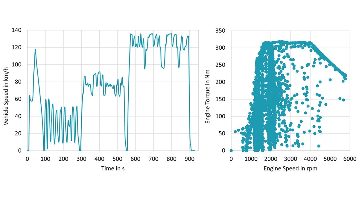
- As was the case with Euro 6d, the specified limits apply to the real driving emissions (RDE). Euro 7 could greatly expand the region in which RDE tests are run in the future and thereby allow significantly more operating points on the engine map to be used, as shown in Figure 1.
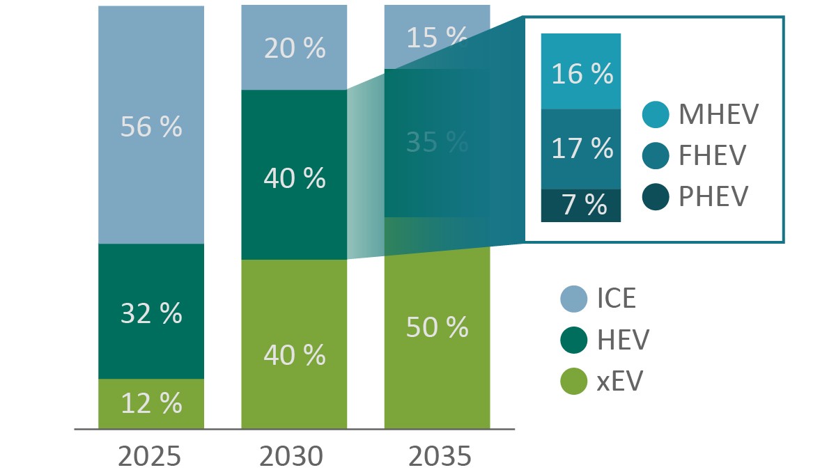
All future hybrid powertrains will need to comply with the upcoming emission limit standards. However, the concrete technical solutions will depend on the actual form that the hybridization takes. According to the current powertrain scenario as seen by Schaeffler, hybrid powertrains will make up roughly 40% of the global market by 2030. If this is further divided as shown in Figure 2, it can be seen that full hybrids and mild hybrids dominate the overall production, with shares of 17% and 16%, respectively. Plug-in hybrids come in at around 7% of the total global market.
Out of the multitude of possible hybrid powertrains, the authors therefore focus in the following on two especially market-relevant configurations: a combined P1/P3 hybrid based on a dedicated hybrid transmission, as presented by Eckenfels and Reitz [1], and the mild P0 or P1 hybrid, in which the electric machine is coupled to the crankshaft of the internal combustion engine.
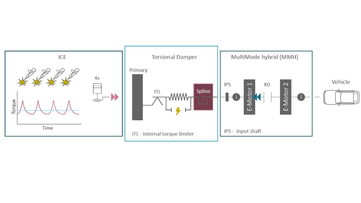
Dedicated hybrid engine for the P1/P3 hybrid powertrain
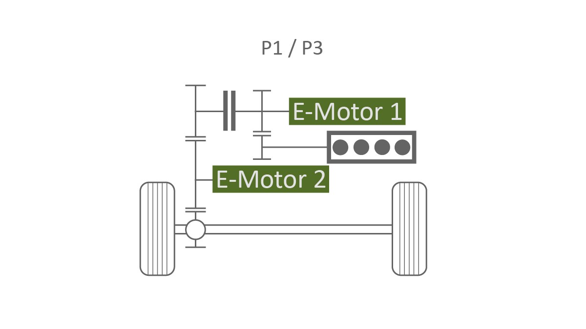
In many of the world’s regions, electrification will mainly be accomplished using full hybrid powertrains in the foreseeable future. For this vehicle category, Schaeffler is currently developing a dedicated hybrid transmission with two electric machines with a combined P1-P3 architecture as shown in Figure 3. The targeted powertrain topology enables three different operation modes: In serial mode, the electric machine in the P1 position solely serves toward power generation and the machine in the P3 position solely serves to provide mechanical propulsion. Because the dual power conversion is associated with losses, a central clutch can be engaged so that the internal combustion engine provides direct mechanical propulsion (parallel mode), which is primarily useful at medium and high speeds. Electric driving, mainly at lower speeds, and recuperation in the deceleration phases are done with the P3 machine with the internal combustion engine shut off.
For the full potential of a dedicated hybrid transmission to be exhausted, a dedicated hybrid engine is needed. The operating regions that the engine with such a powertrain architecture should cover are especially relevant to the design of the internal combustion engine. Figure 4 shows the wheel torques occurring in a typical driving cycle as well as the full-load curves of the P3 traction motor and the internal combustion engine that can be achieved with a nonshiftable mechanical transmission between the internal combustion engine and the drive axle.
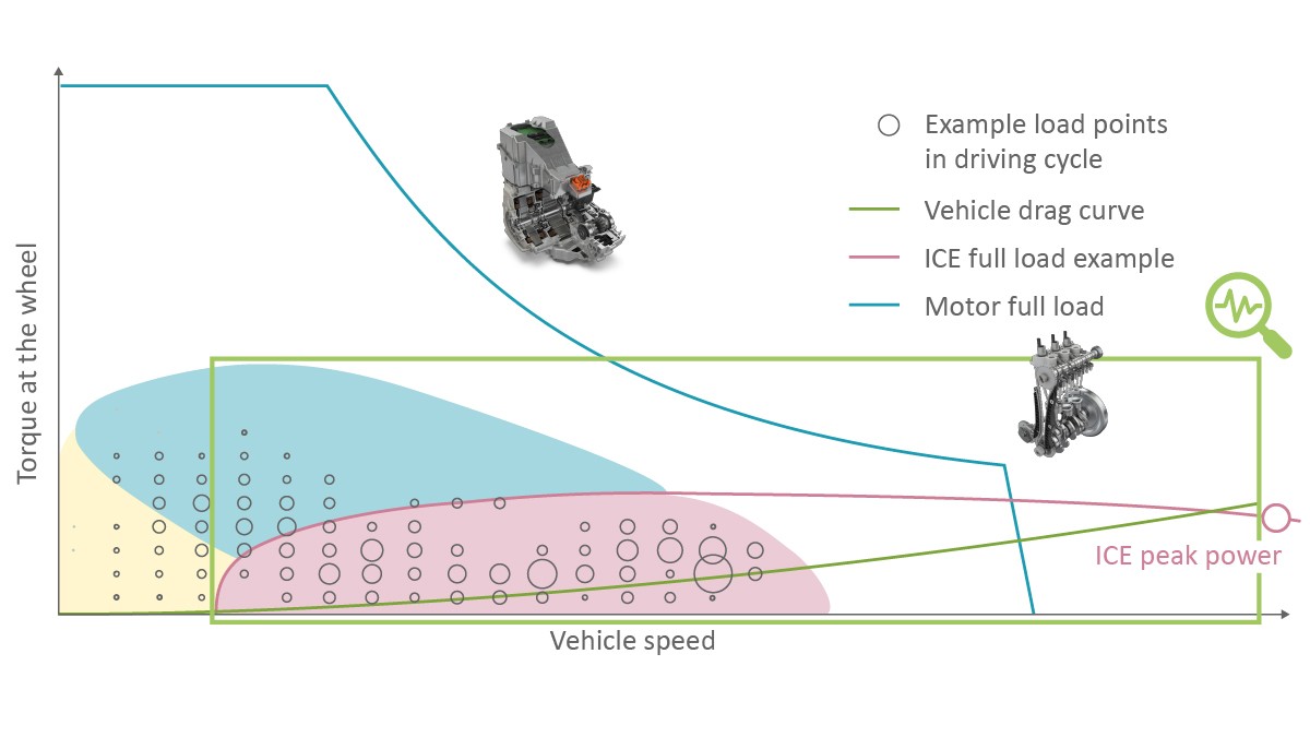
It is clear that with a design with longer gearing, parallel operation at low speeds is impossible. However, with sufficiently long gearing, frequently used operating points such as driving at a constant speed and moderate acceleration or uphill driving lie in a load region in which the internal combustion engine exhibits a good efficiency. A design with long gearing therefore still makes sense because the series powertrain especially shows its consumption advantages through the continuously variable transmission in the electric path where low average power inputs are required.
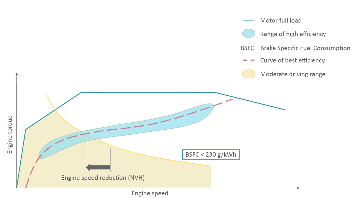
In combination with the dedicated hybrid transmission, the internal combustion engine should be designed for the two operation modes described. For serial operation, because of the continuously variable transmission, operation on the load curve for maximum efficiency (“CVT curve”) is selected. The aim of optimization is accordingly to optimize the specific consumption of the engine along this curve. This requirement could certainly be met by a naturally aspirated engine. However, this would yield relatively high speeds, even at moderate power requirements. Therefore, the curve should be shifted upward to lower the speed level and thus ensure optimum engine acoustics; see Figure 5.
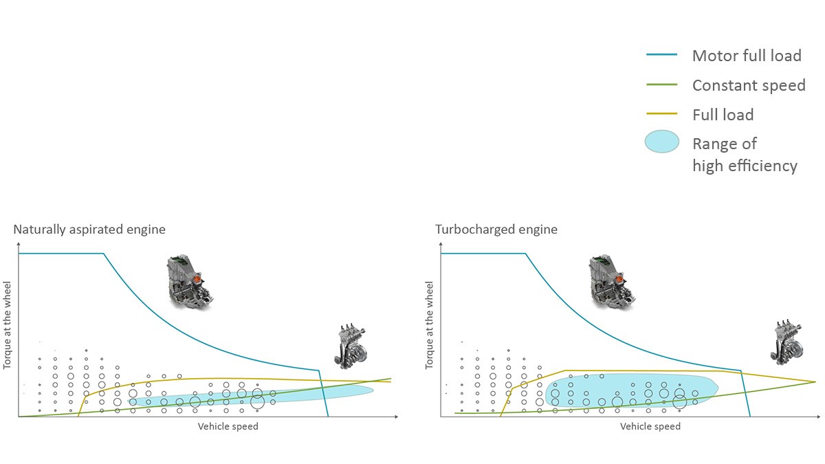
For parallel operation, the engine design is much more difficult. Here, through the fixed-gear transmission, the driving speed and the engine speed are coupled. Through this, the size of the region of the engine map in which parallel operation at a very high efficiency is possible should be maximized. In principle, engines with exhaust gas turbocharging have an advantage over naturally aspirated engines, as shown in Figure 6. A prerequisite for this is avoidance of uncontrolled autoignition (“knock”) at high loads.
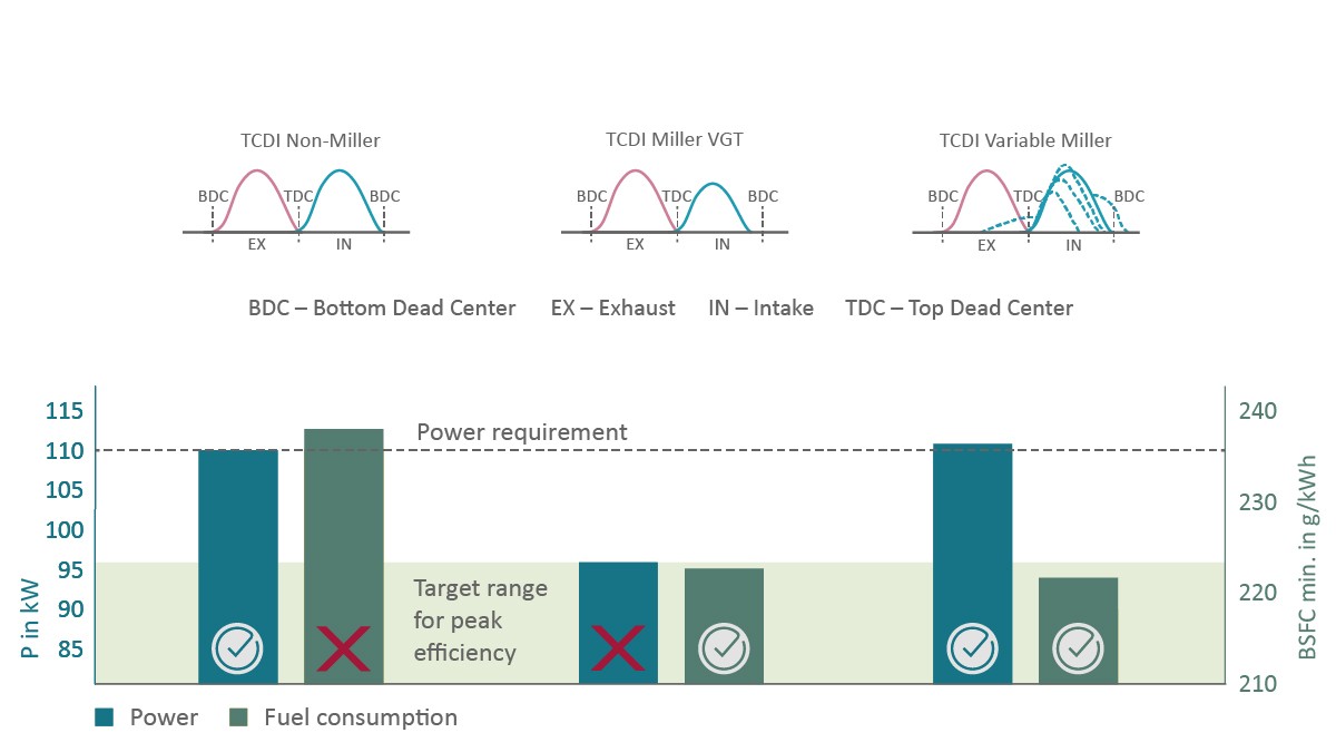
Ideal would be an internal combustion engine that adapts to the operation modes and offers maximum overall efficiency as well as a high level of acoustic comfort. For this reason, the extent to which flexibility in the air path is capable of optimally meeting the different requirements is examined in the following. This flexibility can be achieved via a variable valve train or via a turbocharger with a variable turbine geometry (VTG). To compare the effects of these two measures, Schaeffler conducted investigations on a 1.5-liter Otto engine, which in the mass-produced version has a maximum output of 96 kW and is already equipped with a VTG. The engine was equipped with the fully variable UniAir valve train system and, in return, the variable-geometry turbocharger was replaced with an optimized turbocharging group with waste gate for nearly cost-neutral optimization. The compression ratio was increased from 12.5:1 to 14:1, but still the nominal output was increased to 110 kW, the value required for the concrete transmission, due to the improved knock avoidance.
The mass-produced engine was modified in terms of valve timing and valve lift curves according to the following logic:
- Reduction of pumping losses at low loads through early closing of the intake valve and an optimal internal residual gas fraction through independent variation of the time of opening
- Knock avoidance and an accordingly higher specific power as well as increased efficiency at higher loads through early closing of the intake valve and thus reduction of the effective compression ratio (“Miller cycle”)
- Improved component protection at high power through early closing of the intake valve and thus reduction of the compression end gas temperature
It was shown that despite the noticeably higher power, the specific consumption is lower over the entire map, with the effect being particularly pronounced in the low-load region. A comparable power increase could only be achieved via the VTG with an increase in engine size if the fully variable valve timing were dispensed with, but this would increase costs and power loss, especially in the low-load region. It is also important that in the region of the CVT curve, in which the engine is operating in serial mode, there is no degradation, but rather a slight improvement, in comparison with the basic engine. If this design is transferred to a vehicle equipped with the dedicated hybrid transmission and the fuel consumption is simulated in the typical WLTC cycle, then a consumption advantage of 9.8% over that of a non-Miller-cycle engine of an equivalent output arises, as shown in Figure 7. This consumption advantage is much higher than the average efficiency increases at individual operating points because consumption advantages are also found in the transient operating conditions. An especially precise valve train such as the UniAir System from Schaeffler that can be controlled from one power stroke to the next is needed to leverage this potential.
Vibration damping in dedicated hybrid engines
The dedicated hybrid transmission offers a driving feel in serial operation like that of an all-electric vehicle. Customers also expect correspondingly high comfort in parallel operation. The major challenge here consists in the fact that, first of all, part of the transmission – that is, the electric motor (EM1) that works as a generator – is always permanently coupled to the engine and, secondly, the remaining part of the transmission has less damping mass than a conventional passenger car transmission does. Use of a specially tuned torsional damper upstream of the EM1 is hence absolutely necessary; see Figure 8.
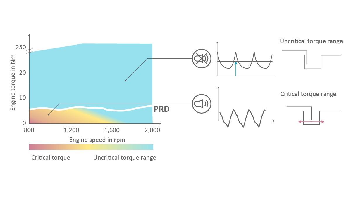
A critical region is presented by low loads in which driving is normally done in electric mode. If the internal combustion engine has to be started, for example, to bring the exhaust gas system up to temperature, the vibration excitation can lead to changed torque directions in the transmission gear teeth. For preventing the noise emissions that result from this, a highly nonlinear design of the damper elasticity is sufficient; see Figure 9. The resultant operating point-dependent variation of the damper stiffness can be adjusted via a lever mechanism (“rocker”).
A malfunction that is particularly critical for the damper design is a misfire in a cylinder, which can never be completely ruled out. The 0.5th-order harmonic occurring in this case leads to excitation of the natural frequency of the overall powertrain system, as shown in Figure 10, resulting in significantly increased amplitudes and especially significant torque nonuniformities on the transmission input shaft. If the damper is pressed into the stop position, the fatigue limits of the shaft may be exceeded.
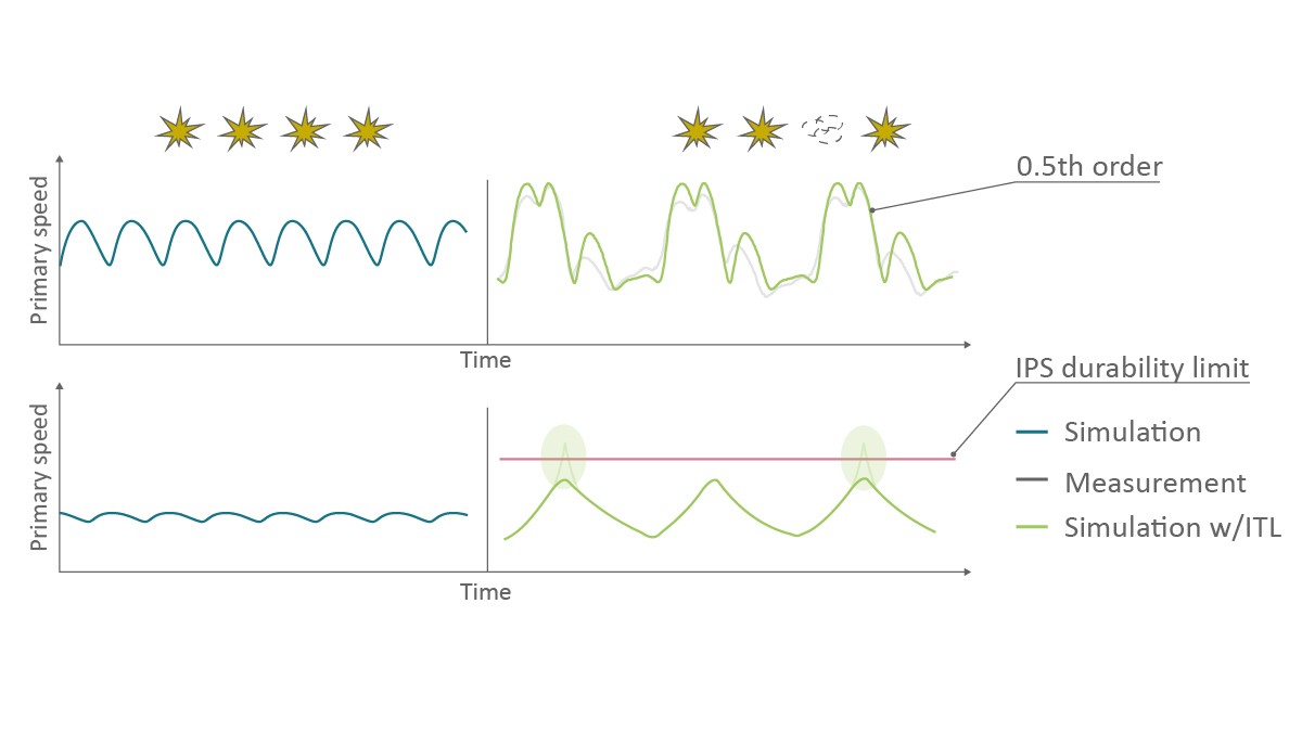
The vibration behavior was reproduced well in simulations. In addition, computational verification that the additional integration of a slip clutch in the damper can sufficiently limit the occurring torque was provided. Starting at a certain torque magnitude, the disengaging clutch provides for decoupling of the engine from the rest of the powertrain so that the excitations can no longer result in torque peaks. A corresponding design was already presented as a solution at the 2018 Schaeffler Colloquium [2].
Dedicated solutions for mild hybrid powertrains
Mild hybrid powertrains in P0 or P1 constellations are in use around the world. They represent a way of noticeably lowering CO2 emissions from existing internal combustion engine powertrains with relatively few adjustments in the form of “upgrades” [3]. From an emissions point of view, a further advantage consists in the lower number of engine starts compared with that of a P2 hybrid powertrain. Systems implemented thus far show two areas in which technical improvements would be desirable:
- The energy recovery capacity to be achieved by mild hybrids is reduced in a P0 or P1 architecture by the drag torque of the internal combustion engine. Decoupling of the internal combustion engine is not possible with this concept, so reduction of the drag torque is an important development goal.
- In overrun mode, pumping of fresh air and thus oxygen from the environment into the exhaust aftertreatment system via the engine is unavoidable. The resulting excess oxygen can have various negative effects on the emission behavior.
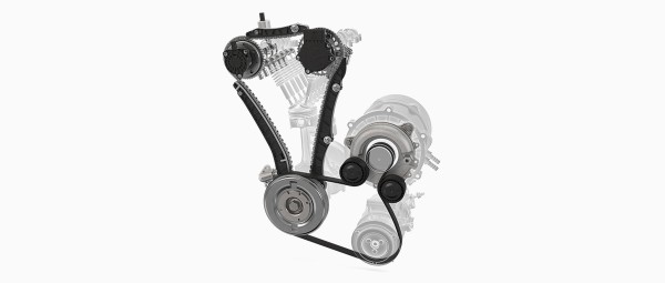
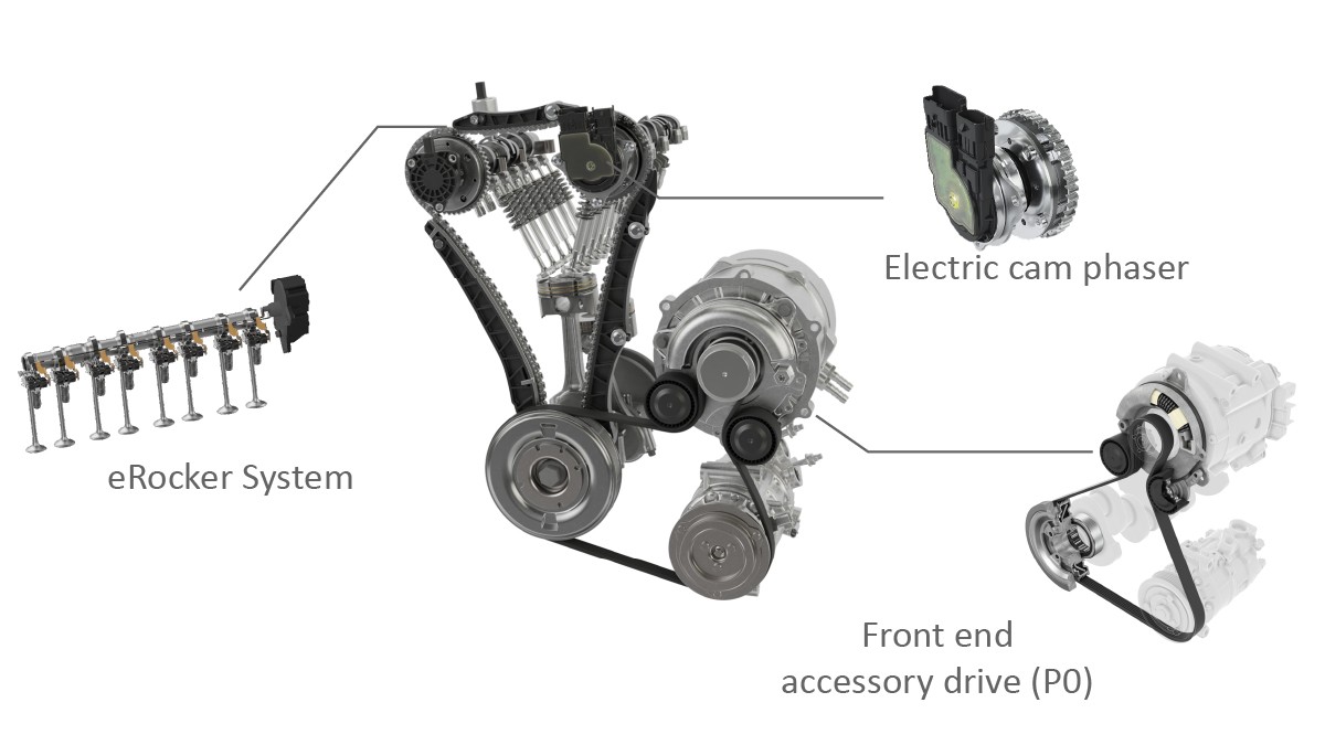
Through application of a technology package that Schaeffler calls the “Smart OverRun System,” parallel optimization of both phenomena is possible [4]; this is described in more detail below. The system consists of an electromechanical cam phaser on the intake side and electromechanically switchable roller finger followers (“eRocker System”) on the exhaust side. In the case of a P0 hybrid, the belt drive between the crankshaft of the internal combustion engine and the electric motor is part of the overall system, as shown in Figure 11, with the belt tensioner designed for frequent switching between traction and overrun modes.
Components of the Smart OverRun System
With an electric cam phaser (eCP), which Schaeffler has been mass-producing since 2015, full decoupling of the phase adjustment from the engine oil circuit and the oil pressure is achieved. Through this, the camshaft position can be very rapidly changed in a large temperature window at all speeds. The electric motor forms a functional unit in combination with a high-ratio, three-shaft variable-speed transmission. The transmission is made up of two ring gears and an oval roller bearing. The electric motor is executed as a brushless electric motor (brushless DC, BLDC). Compared with conventional brush motors, BLDC drives offer a higher efficiency and a longer service life. The motor is connected to a control unit that regulates the motor speed. The sensors integrated in the electric motor detect the position of the rotor and can optionally monitor temperatures. The eCP control unit communicates with the engine control unit via a CAN bus and thus receives the target angle values of the camshaft, which it compares with the actual position. If the phase angle should be changed, the output shaft of the electric motor establishes a speed difference with respect to the gearbox housing. The electromechanical cam phaser switches between the three operating modes of advance timing, constant phase angle, and retard timing. The output shaft rotates more quickly than the camshaft to realize an “advance” timing adjustment (Miller cycle) and more slowly to “retard” timing (Atkinson cycle) when a so-called minus gear is used. Reversal of the adjustment direction via a plus gear has also already been executed. The constant angle is maintained through rotation of the output shaft of the electric motor at the camshaft speed.
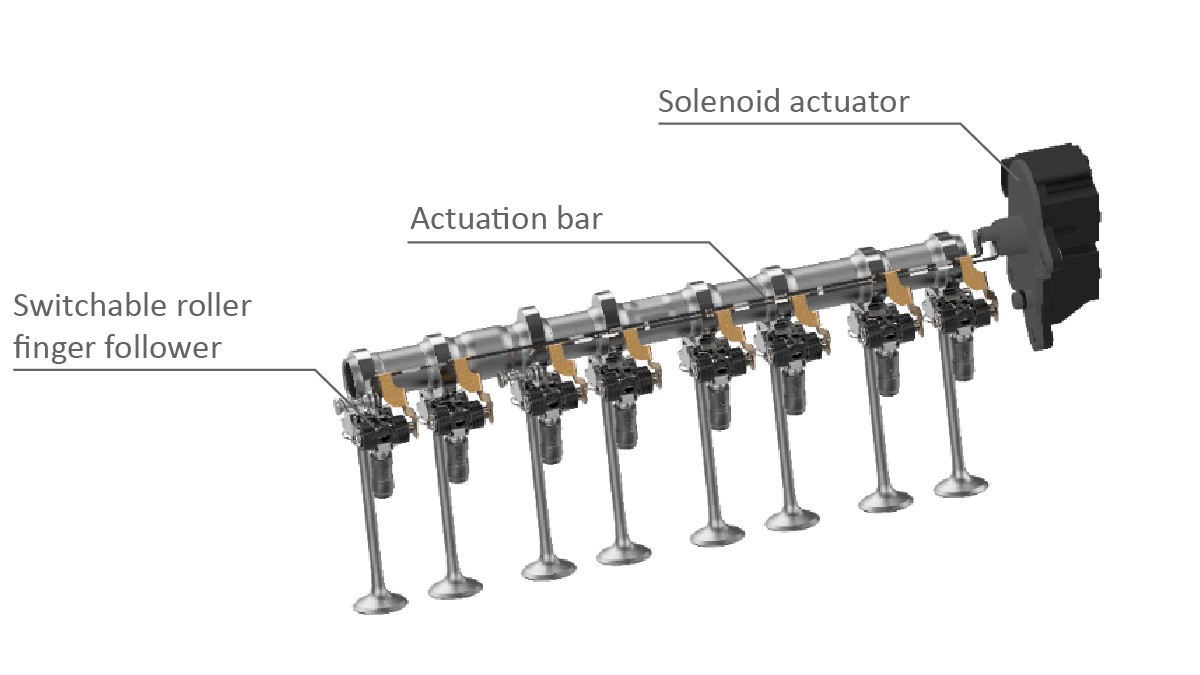
For the actuation of the roller finger follower (eRocker System), Schaeffler employs a central actuator, shown in Figure 12, and avoids complex transmission elements such as adjusting shafts. The actuation occurs mechanically via a slider bar made of sheet metal. The spring arms transfer the motion of the slider bar to the roller finger follower by actuating a shift pin in the outer lever. The pin switches the locking mechanism and releases the connection between the outer lever and the inner lever via an internal shuttle pin mechanism; the lever and thus the valve lift are then deactivated. The switching element, a simple linear actuator, is attached outside the camshaft module or cylinder head. The energy for actuation is stored temporarily in multiple springs. These springs are designed as leaf springs and simultaneously transfer the motion of the actuator bar to the switchable finger follower. Helical compression springs are used as return springs. Additional components are not required. By designing the leaf springs differently in length and cross section, it is possible to assume a position either closer to or farther away from the switchable finger follower in relation to the individual packaging constraints and cylinder head architecture. Mass production of the first engine with the eRocker System from Schaeffler started in spring 2022.
The belt drive, including belt tensioner, plays a critical role in a P0 hybrid. One area of emphasis is the constant further development of the crankshaft belt pulley decouplers. The main focus of more recent developments is on an increased power density and a greater transfer capacity of the decoupler so that even challenging P0 applications can be handled efficiently.
Reduction of drag torque
In order to suppress the mass flow in the overrun mode of the internal combustion engine, it is theoretically sufficient to deactivate the valves on the intake or exhaust side completely. However, this does not automatically lead to a reduction in the drag losses. If, for example, the exhaust valves are deactivated, considerable losses arise through compression of the drawn-in air as well as high pumping losses. Deactivation on the intake and exhaust sides would avoid this problem but requires a lot of hardware effort. An efficient solution is to disable the valves on the exhaust side only and to “retard” the valve timing on the intake side greatly; this results in a low cylinder charge and a low pressure level in the compression stroke. With the combination of the eRocker System and an electric cam phaser, the adjustment ranges and adjustment speeds required for this can be achieved.
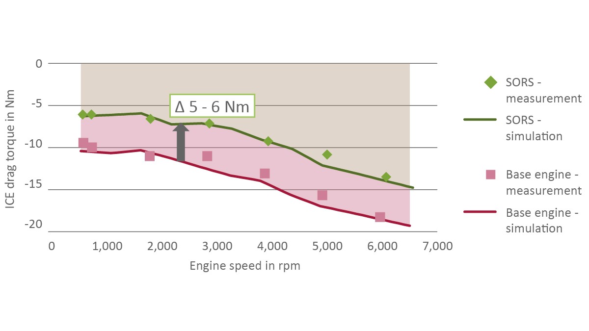
Through this valve train innovation, a significant reduction in the engine drag torque across the entire speed range is possible because the pumping losses can be nearly completely eliminated. For a concretely investigated three-cylinder engine with a displacement of 1.0 l, this resulted in a drag torque reduction of 5–6 Nm, which was confirmed by measurements at individual operating points; see Figure 13. Various simulation runs with different engines show an average reduction in drag torque of up to 50 %.
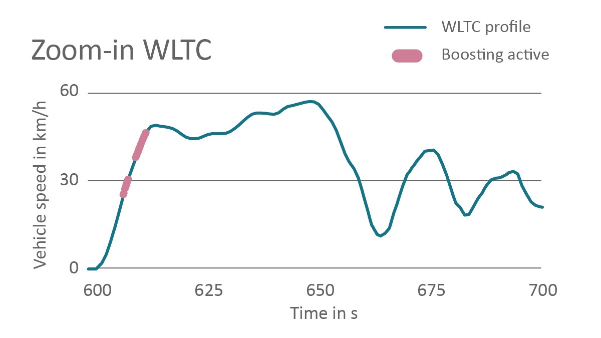
If these savings are transferred to the operating conditions occurring in the WLTC measurement cycle, an increase in energy recovery capacity within the performance limits of the electric machine can be seen. In addition, the portion of the time in which recuperation makes sense is increased. Simulations conducted at Schaeffler for a C-segment vehicle with a 1.0-l Otto engine and a 15 kW electric machine (48 V) with a 500 Wh battery pack show that the Smart OverRun System allows 9 % more electrical energy to be recovered over a complete WLTC driving cycle. There are two possible uses for the temporarily stored power. In one approach commonly used today, the electric machine supports the internal combustion engine in acceleration phases as a “booster” as shown in Figure 14. Due to the limited electrical power of a mild hybrid, the additional CO2 savings to be achieved is limited to 1.1 % here.
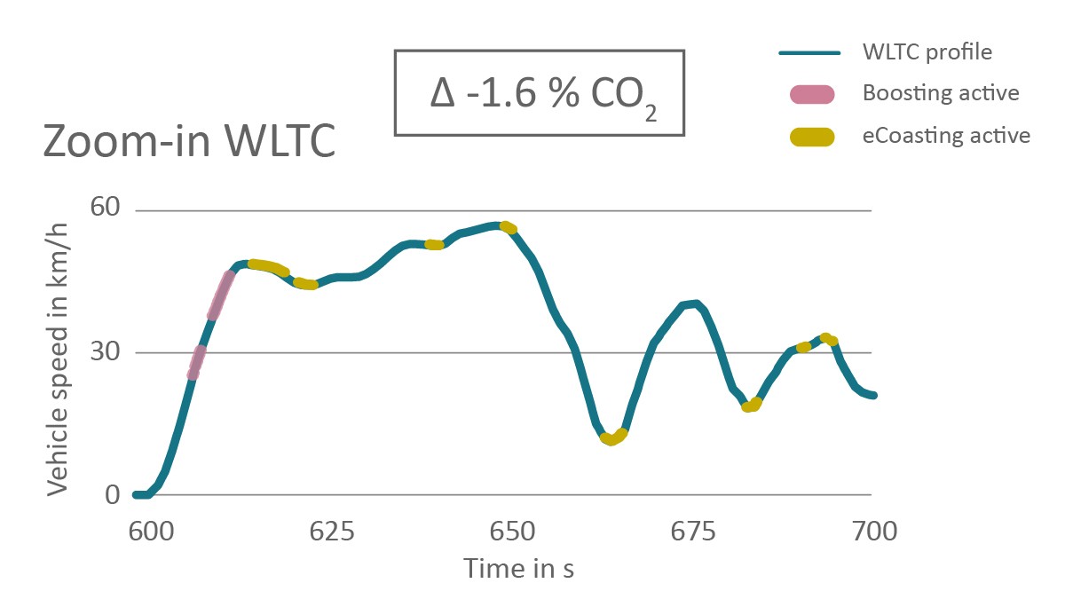
In contrast, in the concept favored by Schaeffler, the electric machine is used to avoid low-load phases in which the internal combustion engine has a very low efficiency due to the throttling losses, among other things. Thus, despite the low continuous output, the electric motor is used as a sole propulsion system in these phases with the internal combustion engine shut off; this only makes sense energetically due to the reduced drag losses. Figure 15 shows that such phases in the WLTC occur relatively frequently – and not just at low driving speeds but also when a relatively high speed should be maintained. Through a corresponding operating strategy, at least 2.7% CO2 can additionally be saved; this is in addition to the savings that would be achieved anyway with use of the hybrid system without the Smart OverRun System.
Reduction of exhaust emissions
In addition, the Smart OverRun System reduces the cooling of the exhaust aftertreatment components and the resultant thermal-mechanical loading. However, above all, the excessive oxygen enrichment in the exhaust aftertreatment system that otherwise occurs in overrun conditions is prevented, so there is no enrichment after the overrun phases and the associated emission peaks are avoided. Figure 16 shows that for the example of an E-segment vehicle (type approval according to emission standard EU6d-ISC-FCM) with a total weight of approx. 2 t, the cumulative CO emissions over the entire driving cycle are lower than those of a current mass-produced vehicle. A comparable effect on the NOx emissions was demonstrated for other engines. Because the effects depend strongly on the engine calibration and the exhaust aftertreatment, a general statement regarding CO or NOx savings cannot be made.
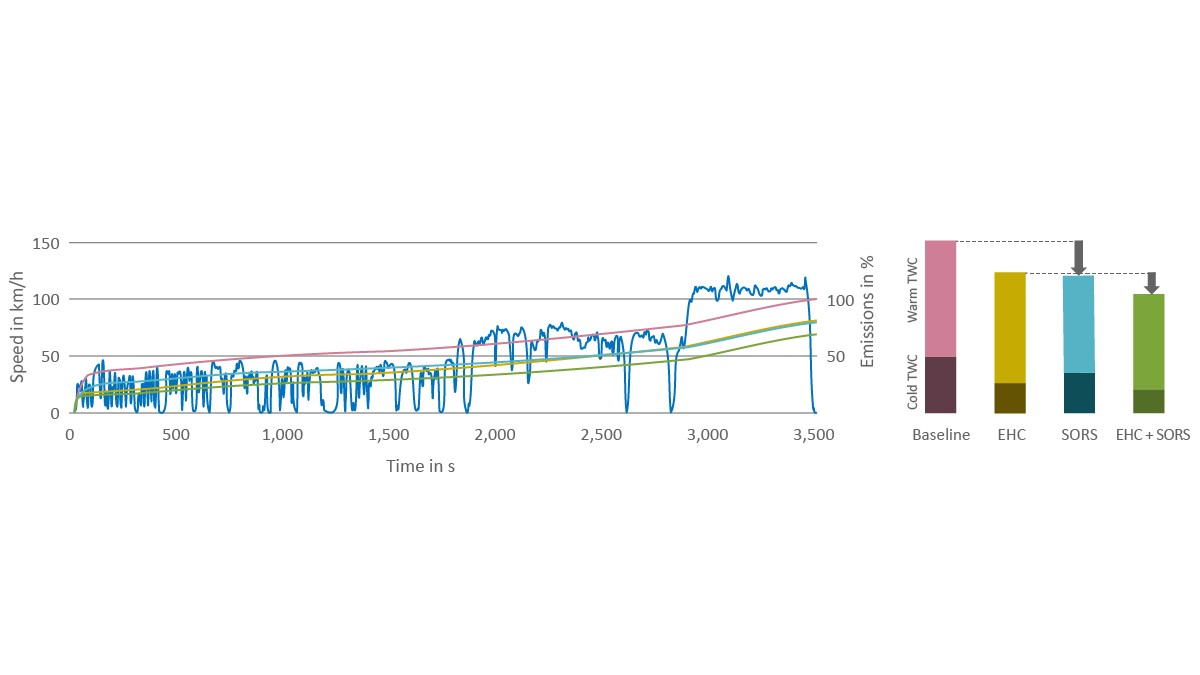
For the Euro 7 legislation, it is expected that both low outside temperatures (for example, down to -7 °C) and dynamic driving profiles with numerous short overrun phases will still be rated as normal operating conditions with the correspondingly low limit values. This makes both the cold start and the overrun phases highly relevant to the overall emissions. As to be expected, the use of an electrically heated catalytic converter enables a significant reduction in emissions immediately after the cold start, whereas the rest of the cycle is practically unaffected. Through use of a Smart OverRun System, enrichment after the overrun phases and after restart can be avoided, thereby resulting is lower CO emissions, as shown in the yellow line in Figure 16. The unrestricted usability of the eCP also allows for an optimized heating strategy. The Smart OverRun System can be combined with an electrically heated catalytic converter so that the advantages are added together.
This enables, in addition to the advantages of the Smart OverRun System already described, precise control of the internal exhaust gas recirculation by fast electromechanical camshaft phasing in transient operating conditions. The residual gas fraction in the cylinder can thereby be set more rapidly and precisely. The consumption effect to be achieved with this is dependent on numerous individual engine parameters. Based on numerous in-house simulations, Schaeffler estimates the average reduction in fuel consumption to be slightly more than 1%. One side effect is the high adjustment speed when Atkinson-cycle naturally aspirated engines are used in hybrid vehicles. Especially late intake valve closing is possible without jeopardizing the restart capability because the start timing can be set again very quickly. This applies over the entire temperature range.
Overall CO2 advantage
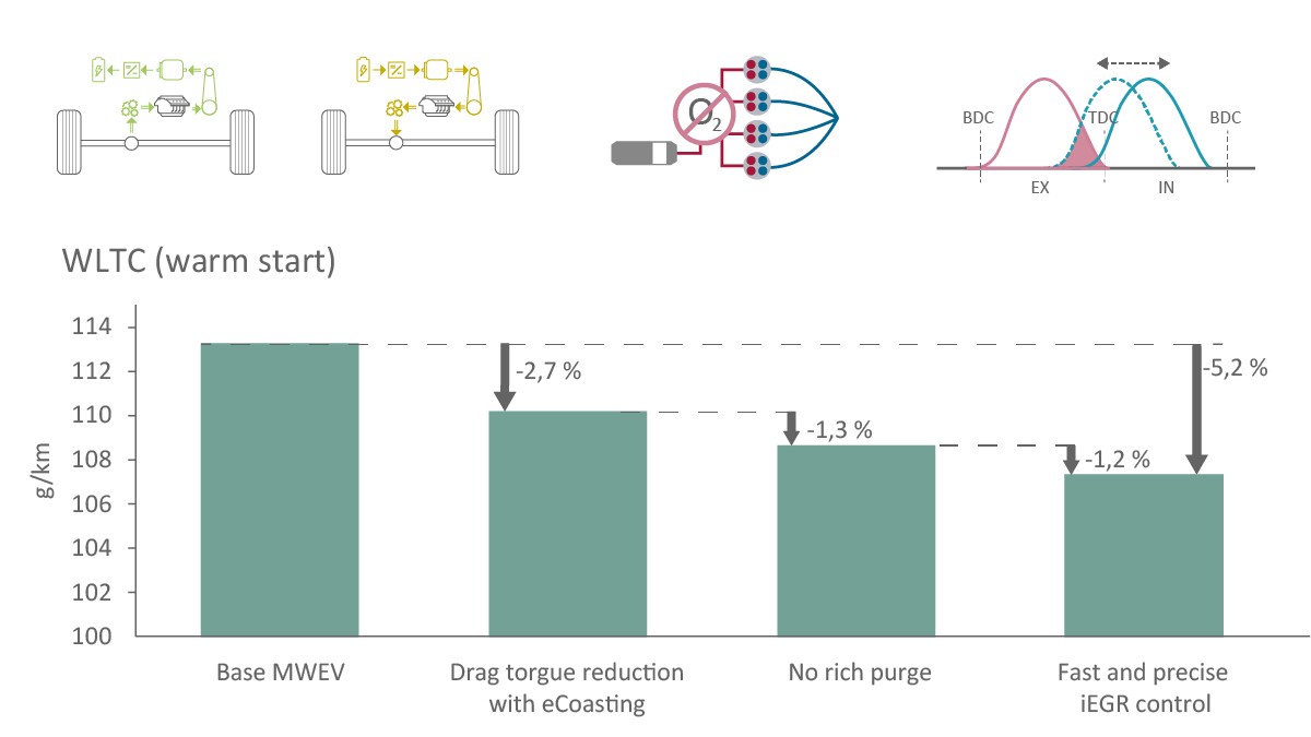
If the Smart OverRun System and the aforementioned operating strategies are applied to a C-segment vehicle with a mass of 1345 kg, a WLTC simulation yields considerable CO2 savings of 5.2%, as shown in Figure 17. The basic vehicle is equipped with a 1.0 L three-cylinder turbocharged engine and P0 hybridization with a 15 kW electric motor, so only the additionally achieved CO2 advantage is shown here. The largest individual contribution, at 2.7 percentage points, is offered by purely electric driving in low-load phases of the cycle, which can be done with a much lower drag torque due to the combination of the eRocker System and the electromechanical cam phaser. Another 1.3 percentage points result from the avoidance of the excess oxygen after restart of the internal combustion engine. The more precise control of the internal exhaust gas recirculation made possible by the fast-switching cam phaser adds another 1.2 percentage points. If an equally powerful electric motor on the crankshaft is used instead of the P0 hybridization, even better values can be achieved because tribological losses in the belt drive are eliminated.
Conclusion
Because powertrains introduced on the market in many of the world’s regions will mainly be electric in the foreseeable future, the next engine generation will have to be conceived right from the start as part of a hybrid powertrain system. These dedicated hybrid engines will have to comply with emission limits set forth in standards such as Euro 7 for real driving emissions. In light of this, Schaeffler has developed new engine technologies for the world’s most common hybrid configurations: a combined P1/P3 hybrid based on a dedicated hybrid transmission and the mild P0 or P1 hybrid, in which the electric machine is coupled to the crankshaft of the internal combustion engine.
The dedicated hybrid engine combined with a dedicated hybrid transmission should be designed for two different operation modes. For serial operation, the aim is to optimize the specific consumption of the engine in a narrow map region, while parallel operation requires a larger region with a high efficiency. Using a current mass-produced engine as a starting point, Schaeffler demonstrates that these requirements can be met with single-stage turbocharging and a fully variable valve train system at an attractive cost. Through specific design of the torsional damper with an integrated slip clutch, the endurance limit and comfort requirements for such a powertrain in all operating conditions can be met.
For mild hybrid powertrains, Schaeffler deploys the Smart OverRun System, which combines electromechanically actuated switchable finger followers and an electromechanical cam phaser with a suitable belt drive. This technology package allows CO2 savings of more than 5% and significantly lower pollutant emissions to be achieved when compared with a P0/P1 hybrid powertrain without additional measures.
Dedicated hybrid engines yield superior results both in terms of driving comfort and with respect to environmental aspects and represent the culmination of 150 years of development history.
[1] Eckenfels, T. et al.: Innovative Hybrid Transmission With Electric DNA. Bühl: Schaeffler Kolloquium, 2022
[2] Faust, H.: The Transmission: Even in the Future, the Most Efficient Link Between Powertrain and Road. Baden-Baden: Schaeffler Kolloquium, 2018
[3] Eckenfels, T. et al.: 48-Volt Hybridization: A Smart Upgrade for the Drive Train. Baden-Baden: Schaeffler Kolloquium, 2018
[4] Werblinski, T. et al.: Valve Train System for P0 and P1 Hybrid Powertrains. 30th Aachen Colloquium Sustainable Mobility, 2021
[5] Himsel, F.: Schaeffler eRocker System: New Concepts for Switchable Finger Followers. Baden-Baden: Schaeffler Kolloquium, 2018
[6] Haas, M.; Piecyk, T.: Valve Trains for Implementing Innovative Combustion Strategies. Baden-Baden: Schaeffler Kolloquium, 2014
[7] Mayer, A. et al.: Combined Miller-Atkinson Strategy for Future Downsizing Concepts. In: MTZ (2018), No. 7-8, pp. 60–66
[8] Demmelbauer-Ebner, W. et al.: The New 1.5-Liter Four-Cylinder TSI Engine From Volkswagen. In: MTZ (2017), No. 2
[9] Kehr, D.; Wolf, D.: Airpath Flexibility – Unlocking the Full Potential of the UniAir System. Baden-Baden, Schaeffler Kolloquium, 2018
[10] Scheidt, M. et al.: Valvetrain Solutions for Flexible Engine Families – Highest Optimization. 42nd International Vienna Motor Symposium, 2021