
Acoustic Optimization of Electrified Powertrains
Dr. Carsten Mohr
The silent manner in which electric vehicles glide is frequently regarded as one of their key selling points. As is inherent to their design, however, electric powertrains do generate tonal noises at a higher frequency. For this reason, it is important to obtain a reliable estimate, early on in the development stage, of the impact electrical components will have on the subsequent sound pattern in the interior of the vehicle. Time-consuming “troubleshooting” in later development phases can only be avoided by performing acoustic optimizations at an early stage. Schaeffler has developed a chain of development tools for this purpose, which can be used to predict perceptible noise at an early stage and to break sound pattern targets down into individual components. The entire tool chain was validated on a demonstration vehicle complete with Schaeffler e-axle; this involved performing a noise synthesis based on component measurements as well as a full simulation and audible rendering of the noise in the interior of the vehicle with incorporation of background noise. There is a high level of agreement between the simulated and actual vehicle interior noise measured, thereby confirming the fundamental function and informative value of this ambitious development approach, which will consequently play a supporting role in all future development projects.
Acoustic development at Schaeffler
Every noise is inevitably the bearer of a message, which the hearer automatically associates with a mental image of its source. A classification is made, usually on the basis of existing experiences, but often also in the subconscious, as to whether the noise has a positive connotation or is associated with something rather more negative, potentially even with a defect. Particularly in the world of vehicles powered by an internal combustion engine, tonal noises such as whistling or buzzing were largely unusual and had negative associations. For this reason, particular attention is now being devoted to optimizing the acoustics of electrified powertrains, so that the tonal noises occurring at higher frequencies and which are inherent to the design of electric motors, do not lead to unpleasant and irritating noise in the interior of the vehicle.
Schaeffler was faced with similar requirements in the past when developing transmission components such as the dual mass flywheel (DMF) or CVT transmission, and is now systematically applying the acoustics expertise gained in simulation and measurement over more than 30 years to electrified powertrains. Thanks to a comprehensive understanding of the systems involved, robust limit curves, which are capable of satisfying the demands set out in the requirement specifications of various applications, can already be defined at a very early development stage, Figure 1. The robustness of a limit curve is linked to the fact that the tolerance deviations, which are unavoidable in the context of volume production, or the scatter for the vehicles produced do not lead to an inadmissible overrun, but do also guarantee the desired acoustic behavior in the entire vehicle.
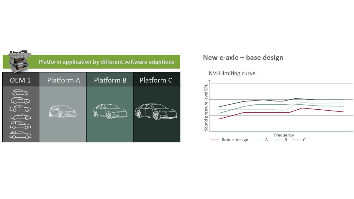
Only by such means can time-consuming and costly troubleshooting be reduced to a minimum. Ideally, the individual tailoring to various vehicle platforms can be achieved through different software adaptations, which will then permit scaling across all models and manufacturers as a part of Schaeffler's modular concept strategy and thereby unlock cost advantages for vehicle manufacturers.
Naturally, the use of predefined limit curves in the development of drives for completely new vehicle concepts is not without its limits. A closer cooperation between manufacturers and drive suppliers is key to achieving a more targeted result. In the event information relating to the entire vehicle is not yet available or is not authorized for onward distribution, Schaeffler can draw approximate conclusions about NVH in the earliest development stage, and set the right course in the development process, by drawing on a continually growing, extensive wealth of knowledge in combination with various databases.
In order that the component limit value which is important to the system supplier can be determined as an acoustic variable from a customer requirement governing subsequent vehicle interior noise, the entire physical event chain for noise formation must be traced backward. This allows the target value for the complete vehicle to be broken down at individual subsystem or component level. An overview of the cascade of methodical steps used is provided in Figure 2.
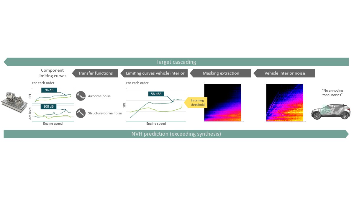
The starting point of the development process is interior noise. If a new drive is to be developed for an existing target vehicle, measured values can be used. If both the vehicle and the powertrain are being developed from scratch, a comparable reference vehicle (the previous model, for example) can be used. The background noise of the reference vehicle can also be modified if necessary, for example if it is already known that a further reduction in wind noise is to be achieved in the new vehicle generation. First, all masking background noises are extracted from the interior noise of the later target or reference vehicle, such as the wind and tire noise that occurs when driving in electric mode. These masking noises are used with the specific aim of preventing the noise components, which are generated by the electric motors, transmission, or power electronics system, for example, and transmitted into the vehicle interior, from becoming noticeably distracting. This is achieved through the definition of masking thresholds, which are able to describe the point at which an individual tone can be heard, i.e. is deemed perceivable, over a buzzing background noise for example. Schaeffler uses in-house evaluation criteria for this purpose; any audible sounds of this type are grouped according to the varying levels of irritation they induce, thereby ensuring the noise quality defined in advance with the customer for the interior of the vehicle. Once the tolerable levels of these sounds have been determined for the interior, the airborne and structure-borne noise limit curves can be determined for the components which are to be measured on the test rig using the transmission functions between the drive and vehicle cabin.
This methodology can also be applied in reverse to predict, at an early stage in the development, the effect that component noise will have on the sound pattern in the interior of the vehicle. In order to achieve this, the environment-independent noise emission of each component must be determined and the transmission behavior of the respective component noise must be known, with a distinction made between the airborne noise path and structure-borne noise path. On the structure-borne noise path, structural vibrations must either be insulated, i.e. prevented from spreading, or dampened, whereby they are stripped of vibration energy by means of dissipation. On the airborne noise path, the airborne noise emitted by the component is transmitted as “component noise”. Insulation or damping can also be used here to achieve frequency-dependent attenuation during the transport of energy. The overall product of this process is the quantitative sound contribution of the individual components in the vehicle interior – also known as “sound synthesis”. Ultimately, conclusions about the overall vehicle interior noise, and resulting statements on noise perception or on the irritation caused by a component element, can only be drawn by factoring in realistic background noises (such as wind or tire noise) as masks.
Application examples
Optimization of a dedicated hybrid transmission
With a dedicated hybrid transmission, also known as a "MultiMode transmission", Schaeffler is pursuing a further significant development in hybrid powertrains [1], Figure 3.
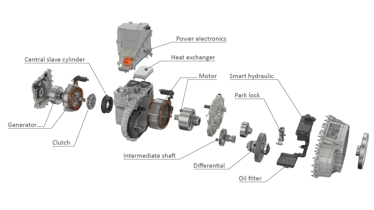
The structure, which comprises two electric motors, a central clutch, and a fixed, non-switchable transmission ratio, has been selected in such a way that the following operating modes are possible:
- direct mechanical drive by the internal combustion engine,
- driven by electric/traction motor in P3 position with internal combustion engine running, while the generator in P1 position provides the necessary energy,
- driven solely by electricity by the P3 machine using the electricity stored in the battery.
One of the key challenges faced in vibration technology terms was that a fundamental statement on the potential effect of occurring electromagnetic forces on structural vibrations had to be made at a very early stage without access to 3D design data.
The analysis program “VibStaSim”, developed specifically by Schaeffler for stator design can be used to determine the coupling effects that may occur between the electromagnetic force modes and the vibration modes of the structure for various parameter variations, such as the number of slot/pole pairs. If these effects show agreement in terms of their formation and number of vibration antinodes, this will result in resonant effects which, from an acoustic perspective, must be avoided at all costs. The motor arrangements responsible for a specific force deflection pattern increase with speed here, while the structural deflection patterns each occur at a specific, fixed frequency. The correct combination of EM configuration and structure dimensioning can be used in this very early design stage to shift resonance couplings of this kind, for example, to such high speeds that they are no longer in the operating range of the drive. The special feature of this internally developed tool is its use of analytical formulae, which permits a comparison of hundreds of electric motor variants, including their acoustic evaluation, in a matter of seconds.
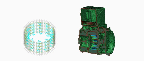
As soon as the EM configuration has been defined in terms of the number of slots and pole pairs, optimization of the electric motor excitation begins. If we consider the effect of the electrical forces on the vibration behavior of the entire unit, we can see that this is largely determinable by the tangential forces in the lower speed range, while the effect of the radial forces dominates at high speeds, Figure 4.
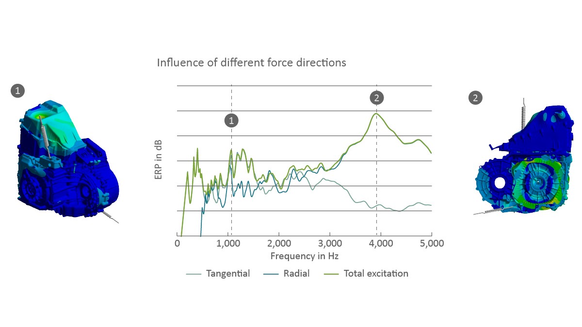
The optimization of electric motor excitation therefore requires an analysis of two different force directions at different speeds. Any modifications should also be reconciled with the unchanged high efficiency and performance requirements. This results in the task of a multi-dimensional, multi-physics optimization, which can be implemented with particular efficiency using meta-modeling. The best possible compromise that can be achieved here as a result is by combining a multitude of individual optimization parameters, which allows the usual conflict of targets between good acoustic behavior on the one hand and high efficiency on the other to be resolved to a certain extent.
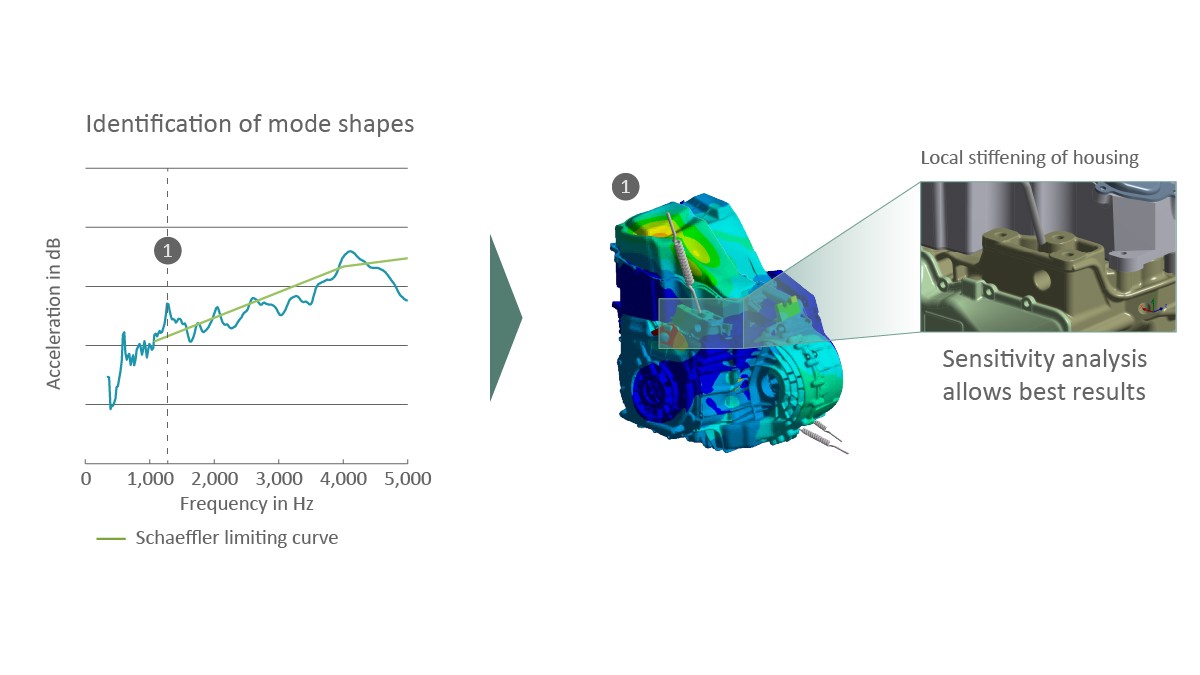
If the electric motors have already been optimized in terms of their excitation behavior, the response to these force excitations, i.e. the vibration behavior of the housing structure, is examined in the next step. The previously defined limit curve represents the essential assessment criterion in this respect. If this curve is exceeded at individual points, it is essential to identify the responsible deflection forms in the structure in order that specific, localized reinforcement of the structural geometry can then be carried out, Figure 5. A sensitivity analysis makes it possible to limit the necessary modification parameters, e.g. for ribbing, in such detail during the preliminary stages that these remedial measures can usually be implemented without any impact on mass or design envelope.
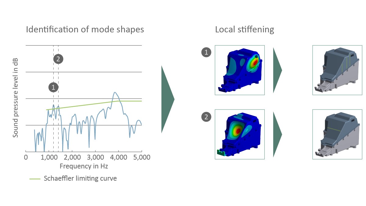
If the excitation by electric motors and transmission thereof in the form of structural vibrations is minimized, a further step is taken to reduce airborne noise emissions. By coupling a fluid model with the surface vibrations of the housing, the emitted airborne noise is determined and compared with the frequency-dependent limit curve. In a similar way to the structural optimization, it is also important to clearly identify the responsible emission surfaces where values are exceeded, in order to permit local modifications to the housing, Figure 6. Small geometric changes, such as the reinforcement of larger surfaces, can reduce airborne noise emission and ensure adherence to limit values.
Optimization of the tooth set on an axle drive
In Schaeffler's electric axle drives, the electric motor, power electronics system, and transmission form a single unit. In contrast to vehicles with a combustion engine, gear noises occurring in the transmission of a purely electric vehicle are not masked by the combustion engine. This is also combined with an increase in customer requirements for a pleasant and quiet interior noise level. Numerous individual parameters are known for use in the acoustic optimization of gears, from the transverse contact ratio through to tooth flank modification. However, as contact ratios cannot be increased arbitrarily and the changes in geometry at the tooth flanks only have an optimal effect in certain load ranges, optimizing excitation alone is not sufficient in many cases to meet the high NVH demands placed on the gearing in connection with electric drives.
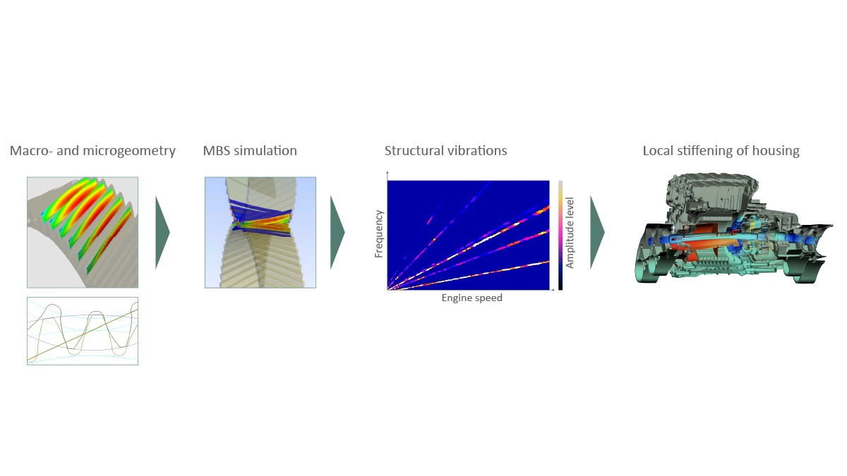
The transmission error of the gearing that remains following the optimization of the macro- and micro-geometry serves as an input variable for the excitation of a multi-body simulation, which can be used to describe the structural dynamic behavior of the entire transmission. In this case also, the analysis of the entire system with the lowest possible excitation, optimized transmission, and minimal emission is of particular relevance, Figure 7. Once again, the development goal is not necessarily to reduce the gear noise to the lowest possible level, but to render it inaudible to the driver, and is therefore precisely why it is imperative that the overall vehicle interior noise, including all background noise, also be considered.
Interior noise prediction
With the aid of a demonstration vehicle, Schaeffler shows that by using the entire tool chain, a reliable prediction of the interior noise perceived by the driver can be made in an early development phase. Using a newly developed procedure, the cutting forces transmitted at the coupling points of the components can be determined on a quantitative basis in the fitted state and converted into so-called blocked forces. The special feature of these blocked forces lies in their excitation size, which is independent of the system, and, as a result, in their suitability as input data in combination with the emitted airborne noise for a transfer path model of the vehicle. As a result, the airborne and structure-born noise excitation are analyzed separately with their respective transmission paths and synthesized as noise contributions for the vehicle interior noise. The subsequent speed-synchronous overlap with a background noise originating from the database can be used to provide a realistic simulation of the complete sound situation in the vehicle interior. In addition to rendering sound audible, this method also makes it possible to assess both the noise quality and the level of irritation caused by the individual noise components.
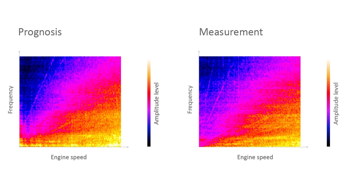
In addition to a description of component excitation at the correct level and transmission thereof into the vehicle interior, a detailed representation of the tire and wind noise as a function of vehicle speed is also vital to the quality of this interior noise prediction. A comparison of the interior noise predicted in this manner for a demonstration vehicle using the conducted interior noise measurement shows very good agreement, Figure 10.
The use of the chain of development tools described at the start permits a comparison of different variants with justifiable computational effort, resulting in a paradigm shift in the acoustic development of drive components away from “as quiet as possible” to “as quiet as necessary”. Such an approach can help to increase market acceptance of electric drives through the associated resource efficiency.
Summary
From the customer's perspective, acoustic comfort is a key quality feature of hybrid and electric vehicles and one in which the interior noise perceived by the driver plays a decisive role. The noise generated by individual components in the drive only plays a role in this if it is not masked by other noise components or driving noises. For this reason, Schaeffler is adopting a complete vehicle approach to acoustics development and has expanded both its expertise and in-house test facilities.
The definition of frequency-dependent limit curves for individual components and subsystems has proven successful in applying the requirements for vehicle interior noise to their respective development.
If the boundary conditions for components developed in accordance with functional and economic criteria cannot be observed, the first step is to try to reduce the excitation. In accordance with the physical chain of events, subsequent optimizations will then focus on transferring this acoustic excitation and ultimately on the response behavior of the structures, such as the housing. By localizing acoustically relevant structures, optimizations with no impact on mass and design envelope can often be achieved here. Both the airborne noise emission emanating from the housing, and the structure-borne noise introduced into the vehicle structure as vibrations at the connection points, determine the sound contribution made by the component to vehicle interior noise. Ultimately, a realistic auralization of the vehicle interior noise and resulting prediction of the noise quality is only possible if all background noise is taken into account.
Using various electrical drives a dedicated hybrid transmission, and an electric axle drive – the paper shows how Schaeffler converts the high requirements at vehicle level into the specific acoustic optimization of components. An accurate prognosis of the resulting vehicle interior noise contributes significantly to increasing resource efficiency in acoustic development.
[1] Eckenfels, T. et al.: Innovative Hybrid Transmission With Electric DNA. Bühl: Schaeffler Kolloquium, 2022